WEEK 1FLUID POWER
TODAY, THE FOLLOWING WILL BE COVERED:
+ NATURE OF THIS COURSE;
+ SYLLABUS FOR COURSE;
+ BASIC FOUNDATIONS OF FLUID SYSTEMS: TERMS, UNITS, RELATIONSHIPS.
Bold denotes IMPORTANT TERMS !
INSTRUCTIONAL OBJECTIVES:
A. Develop an understanding of some basic principles:
I. Pascal's Law
1. Pressure
a. head b. atmospheric c. gage
2. Force
3. Area
4. Density and Specific gravity
II. Mechanical and Hydraulic leverage
III. Basic Hydraulic Circuit
1. Hydraulic jack
2. Linear hydraulic circuit
B. Dimensional calculations - English and Metric systems
I. Units for:
1. Length
2. Area3. Volume
4. Pressure
5. Force
II. Example Problems for:
1. Head
2. Hydraulic Jack (lever)
3. Linear Circuit (sizing cylinder).
Homework Assignment: See Assignments Web Page.
C.
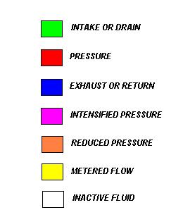
Standard Color Coding for Hydraulic Systems
BASIC TERMS, DESCRIPTIONS, UNITS, AND THEIR RELATIONSHIP.
TERM DESCRIPTION ENGLISH METRIC RELATIONSHIP
HEAD Height of a fluid column ft. m 1 ft. =.3048m
STROKE Length of rod travel in. mm 1 in.= 25.4mm
FORCE Thrust of a cylinder lbs. N 1 lb. =4.4482N
AREA Surface of a piston in.2 mm2
PRESSURE Force/Area lbs/in2 N/m2
or N/mm2
(NOTE: 1 N/m2 is also called a Pascal denoted by Pa.)
(1 PSI = 6895 Pa.)
(1 N/mm2 is also called a Mega Pascal denoted by MPa.)
(1 PSI = .006895 MPa.)
BAR (Average Barometric Pressure) 14.5 PSI = 105 Pa.
VOLUME
Area X Length(height): in.3
or GAL. (NOTE: 1 GAL. = 231 in.3)
or cubic foot ( 1 cubic foot = 1728 cubic inches)
or mm3
or cm3
or m3
or Liter
(NOTE: 1000 liters = 1 m3 )
( 1 liter = 1000 cm3 )
( 1 liter = 106 mm3 )
FACTORS AND PREFIXES
FACTOR PREFIX SYMBOL FACTOR PREFIX SYMBOL
1012 tera T 10-2 centi c
109 gigi G 10-3 milli m
106 mega M 10-6 micro u
103 kilo k 10-9 nano n
102 hecto h 10-12 pico p
10 deca da 10-15 femto f
10-1
deci
d
10-18
atto
a
EXAMPLE PROBLEMS:
1. Find the head pressure
at the base of the storage tank shown if
a) the
tank is filled with fresh water;
b) if
the 20ft. tank is filled with oil having a weight density of 56 lbs./ft.3
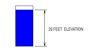
SOLUTION: P= gx h
a. Weight Density for the fluid = 56 lbs/ft3
b.
56 lbs/ft3 x 20 ft. = 1248 lbs / ft.2 x 1 ft.2
/ 144 in.2 = 7.78 psi
2. Find the maximum that can be lifted by the hydraulic jack.
FORCE @ HANDLE (FA) = 20 pounds; SOLVE FORFORCE AT ROD (FB)
CYLINDER 1 = 1/2 INCH BORE (PUMP CYLINDER)
CYLINDER 2 = 4 INCH BORE (WORK CYLINDER)
NOTE: BORE IS THE
INSIDE DIAMETER OF THE CYLINDER.
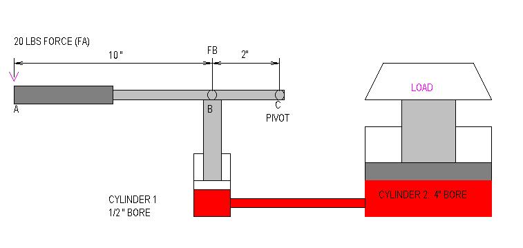
SOLUTION: WORK @ A = WORK @ B OR 20 LBS. X 12 " = FB X 2"
240 LB-IN = 2 X FB, THEREFORE FB=120 LB.
ALTERNATE SOLUTION: Sum the moments about point c.
![]()
FB(2 in.) = 240 lb-in
FB = 120 lb.
AREA OF CYL 1 = .7854 X .5 IN.2 = .19635 IN.2
AREA OF CYL 2 = .7854 X 4 IN.2 = 12.57 IN.2
P=F/ACYL 1 ; P=120 LB./.19635 IN.2 = 611.15 PSI
FCYL2
=P X ACYL2 = 611.15 X 12.57 = 7682.2 LBS.
3. Determine the size (bore)
of the cylinder for the system
shown
below.
SYSTEM PRESSURE = 8 Mpa;
CLAMP FORCE = 36KN
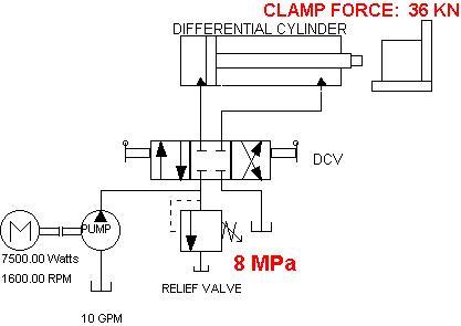
SOLUTION: A=F/P = 36000 N / (8 N/mm2) = 4500 mm2
A=.7854 X (D2)
D= (A/.7854).5 = (4500/.7854).5 = 75.69 mm
+ FLOWRATE, VELOCITY, AREA RELATIONSHIPS FOR LINEAR ACTUATORS;
+ TERMS, UNITS, RELATIONSHIPS;
+
REGENERATIVE CIRCUIT.
Normal Linear Circuit. Under normal operation, the piston velocity (Vp) during the extension mode for a hydraulic cylinder is dependent on the pump flow rate (Q) entering the cap side of the piston and the cap area (Acap) as shown in the general equation below:
Velocity = Flow Rate / Area
Velocity of the piston during the extension phase of motion, can be determined using the formula as shown below:
Velocity
of piston during extension in normal linear mode equation: Vpext
= Qpump
Acap
Similarly, the velocity during retraction is calculated as follows:
Velocity of piston during retraction in normal mode equation:
Vpret
= Qpump
Aan
The time required for a hydraulic cylinder to extend is dependent on
the Stroke (S) or linear displacement of the actuator and piston velocity.
The general equation
is shown below:
Time = Stroke / Velocity
To determine time during extension, the velocity during extension much be substituted into the equation. Similarly, to determine the time during retraction, the retraction velocity must be used.
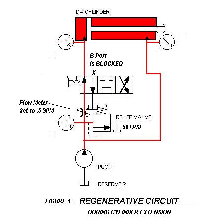
Regenerative Circuit. Regenerative circuits are used
when it is desirable to rapidly advance an actuator into position to reduce
cycle time. When configured as
a regenerative system, cylinders can be advanced more rapidly than
in normal operation with the pump flow rate alone. In order to accomplish
regeneration, the fluid leaving the rod end of the cylinder is routed back
to the cap side of the cylinder to combine with the pump flow rate from
the pump as depicted in Figure 1 below:
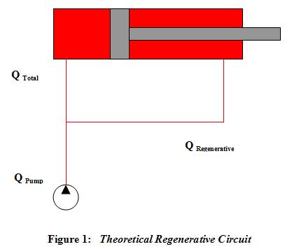
Therefore, QTotal = Q Pump + Q Regenerative.
Solving for Q Pump: Q Pump = QTotal - QRegenerative
Remember that Flow Rate (Q) = Piston Velocity (Vp) x Area.
Substituting the appropriate areas, the equation for Qpump becomes:
Qpump = Q Total - Q Regenerative
Qpump =[Vp x Acap] - [Vp x (Acap - Arod)]
Factoring out Vp, the equation becomes:
Qpump = Vp (Acap - (Acap - Arod)
= Vp (Acap - Acap + Arod)
= Vp (Arod)
Therefore: To find the velocity of piston IN REGENERATIVE MODE, the equation below can be used.
Velocity of piston
during extension in regenerative mode equation: VpRegeneration
= Qpump
Arod
Note: Regeneration circuits are typically only used on cylinders having a single rod and only in the extending direction!
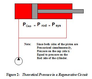
Next we will consider force during extension in
the regenerative circuit. Since both the capside and rodside
are pressurized at the same time,
the pressure in the system is constant and equal
on both the capside and rodside of the cylinder as shown in Figure 2 below:
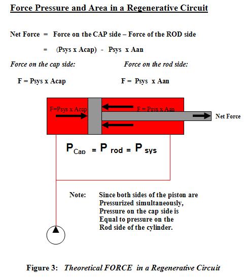
Resulting force available on the external rod is the net force or difference
between the force on the capside and the rodside cylinder. Note that
even
though both sides are pressurized, the force on the capside will be
greater that the force on the rodside due to the cap area being greater
than the annular area.
Force in a regenerative circuit during extension of a single rod, double
acting cylinder is show in Figure 3.
Note: If (and only if) the
ratio of CAP area to ANNULAR area is exactly 2:1, equal speed and force
will result for a
regenerative circuit operating during extension AND a normal linear circuit
operating during retraction.
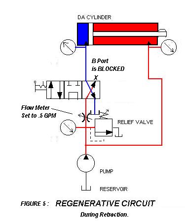
A typical complete regenerative
circuit in extension mode is shown in Figure 4 and retraction mode in Figure
5.
WEEK 3
THE FOLLOWING WILL BE COVERED:
+ Fluid Properties
+ WORK, POWER AND HORSPOWER;
+ Review FLOWRATE, VELOCITY, AREA RELATIONSHIPS FOR LINEAR ACTUATORS;
+ EXAMPLE PROBLEMS
Blue denotes important terms
DENSITY and SPECIFIC GRAVITY
MASS : Property
of a body of fluid that is a measure of inertia or resistance to change
in motion.
The term can also be used as a measure of the "quantity of fluid"
Note: In the Imperial System, the SLUG is used for MASS DENSITY (r).
Since m = F / a; the units = lbs / ft/sec2 = lb-sec2/ ft. Therefore 1 slug = 1 lb-sec2 / ft.
Typically we are more concerned with MASS DENSITY or SLUGS / cubic feet
Example: Suppose a hydraulic fluid has a weight density of 58 lbs / ft3
m = F / a = 58 lbs / 32.2 ft/sec2 = 1.8 lb-sec2 / ft OR 1.8 SLUGS / ft3
For the SI system, the unit of kilogram (kg) is used to denote MASS DENSITY.
The Newton (N) is the standard unit of Force and is defined as 1 kg - m / sec2
Example: A boulder has a mass of 5.75 kg, what is the force in N due to the earth's gravity?
Answer: F = m a = 5.75 kg x 9.81 m / sec2 = 56.4075 kg - m / sec2 = 56.4075 N
Note: On the earth's surface, acceleration
is assumed to be constant, and weight density or specific weight
is typically used. MASS DENSITY is crucial when designing hydraulic
systems for space craft.
WEIGHT DENSITY:
Weight density is defined as specific weight per volume.
In the Imperial system typical units would be lbs / ft3
In the SI system typical units are N / m3
SPECIFIC GRAVITY:
Specific gravity is a ratio of the density of a fluid compared to the density
of fresh water. Specific gravity
can be expressed as a ratio of MASS DENSITY OR WEIGHT DENSITY.
NOTE: The constant for fresh water (weight density) used as a standard is 62.4 lbs / ft3 in the Imperial system
For the SI System, the MASS DENSITY of fresh water is 1000 kg / m3
Therefore the weight density (g) = 1000 kg / m3 x 9.81 = 9810 N / m3
Example Specific Gravity Problem: Find the specific gravity of sea water if the SPECIFIC WEIGHT is 10.1 kN / m3
Answer: 10.1 kN/m3 = 10,100 N/m3 Sg = gsea
water / g fresh
water = 10,100 / 9810 = 1.02956
Week 3
I. Power, Torque and Mechanical Horsepower
Power = Work / time; Torque = Force x distance of moment arm;
HP = Power / Basic Unit of Horsepower (e.g. 746 watts, 550 Foot-lbs./sec, 746 N-m/sec.)
II. Horsepower in Hydraulic Systems
1. Fluid Horsepower
Generic Formula:
FHP = Pressure x Flowrate x C
(C = constant for converting to appropriate units)
English System: FHP = (P X Q) / 17142. Brake Horsepower
where: P = Pressure in PSI
Q = Flowrate in GPMMetric System: FHP = (P x Q) / 44.76
where: P = Pressure in mega Pascals (1 MPa = 1 N/mm2)
Q= Flowrate in LPM (liters per minute)
Note for computations, brake and torque horsepower use essentially the
same formula.
Brake howepower reflects the braking intensity or load placed on the prime
mover (e.g. electric motor).
The formula will be covered below.
3. Torque Horsepower
In hydraulic systems, indicates the horsepower available at a rotary
actuator:
Generic formula: THP = T x N x C (constant for converting appropriate units)
English System: THP = (T x N) / 63025
Where: T = torque in lb-in.
N = rpm
Metric System: THP = (T
x N) / 7121
Where: T = torque in N-m
N = rpm
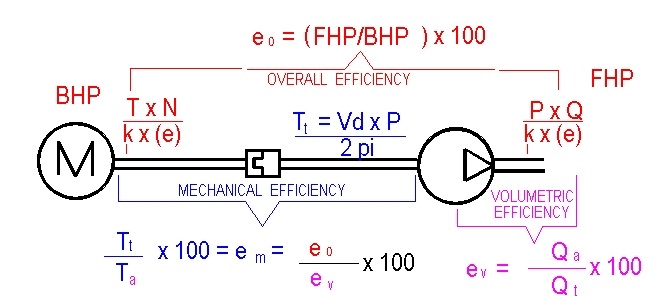
4. Efficiency
Since no systems are 100% efficient, the formulae must me adjusted
to account for losses. Typically,
an efficiency of 80 to 85 % is assumed for hydraulic fluid horsepower.
Therefore the formula becomes: FHP = (P x Q) / (1714 x e)
for English system.
Similarly, efficiency must be included for the metric formula as well as
for THP formulas when
efficiencies are know. More attention will be given to efficiency
when pumps and actuators are covered.
Formulae and Example Problems - English and Metric systems for:
1. Flow, velocity and area
Flow rate (Q) = (V)elocity X (A)rea
Q = V x A; units must be compatible.
Example problem: A cylinder has a stroke (linear movement) of
of .25 meters and must extend in 5 seconds. Cylinder bore is 100 mm.
What is the required flow rate for the system?SOLUTION: A = .7854 x d2 = .7854 x (.1m)2 = .07854 m2
V = Stroke / time of extension
= .25 m / 5 seconds = .05 m / sec.
Q = V x A = .05 m / sec. x .07854 m2
Q = .003927 m3 / sec.
=.003927 m3 / sec. x 60 sec. / min. x 1000 liters/ m3
Q = 3.927 LPM (liters per minute)
2. Power and mechanical horsepower.4. Torque Horsepower.
Example problem: A forklift raises a 2000 lb. pallet 5 feet in 5 seconds.
What is the power output?
Solution: Power = Work / time = (2000 lbs x 5 feet) / 5 seconds = 2000 ft-lbs/sec
How much horsepower is required?
Solution: HP = Power / (Basic Unit of Horsepower)
HP = (2000 ft-lbs / sec) / (550 ft-lbs/sec)
HP = 3.643. Fluid Horsepower.
Example problem: A hydraulic system operates at 10 MPa pressure with
pump flow rate of 20 LPM. What horsepower is required for the electric
motor driving the pump assuming 85% efficiency?
Solution: FHP = (P X Q) / (44.76 x e)
Note the formula requires flow in LPM therefore units are compatible.
FHP = (10 x 20) / (44.76 x .85)
FHP = 4.47
Homework
Assignment: See Assignments Web Page.
THIS WEEK WILL BE DEDICATED TO PROJECT WORK.
+ ORGANIZING WORKSHEETS IN EXCEL
+ EXCEL EXAMPLES: DEALING WITH CIRCULAR REFERENCE
+ Introduction to systems and preparation
for Lab 4 (putting together what we have learned to date).
TOPICS:
+ Review SPECIFIC
GRAVITY
+ Review
WEIGHT DENSITY
+ Review
MASS DENSITY
+ Review
HEAD PRESSURE
+ VISCOSITY
+ VISCOSITY
INDEX
+ BULK MODULUS
NOTE: EXAMPLE PROBLEMS
WILL BE USED TO EXPLAIN THESE TOPICS.
RELATIONSHIP OF SPECIFIC GRAVITY, WEIGHT DENSITY, MASS DENSITY.
Sg = Weight Density of "X" / Weight Density of Water
= Mass Density of "X" / Mass Density of Water
Properties of fresh water will be used as a standard.
VISCOSITY
ABSOLUTE
KINEMATIC
SAYBOLT UNIVERSAL SECONDS
VISCOSITY INDEX FOR RATING THE STABILITY OF A FLUID
BULK MODULUS AND THE COMPRESSIBILITY OF A FLUID
LAB: SYSTEM SPECIFICATIONS FOR AN APPLEJUICE PROCESSING SYSTEM.
(NOTE:
This lab will incorporate virtually everything that has been covered thus
far in this class)
The
purpose of the lab is provide an application for system design, AND to
serve as a review for test one.
TEST ONE
TOPICS
+ BULK MODULUS
Example: Hydraulic feed for a milling machine.
+
VOLUMETRIC DISPLACEMENT (VANE PUMP)
Deriving the formula:
Vd
= Pi/2 (Dc+Dr) (e) (L)
Example problem for a variable displacement pump.
+
VOLUMETRIC DISPLACEMENT (PISTON PUMP)
Deriving the formula:
Vd
= D x A x Y x (tan O )
Example problem for a variable displacement pump.
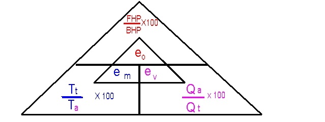
+ EFFICIENCIES AND
RELATIONSHIPS
WEEK 8
TOPIC: PUMPS THEORY AND EXAMPLES (Video tapes)
Review UNIT 3 on Pumps from the following site:
http://64.78.42.182/free-ed/MechTech/hydraulics01/default.asp
Topics:
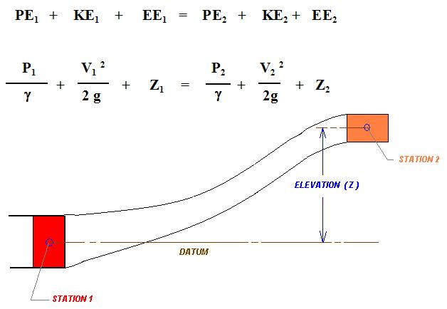
Conservation of Energy
Continuity Equation
Bernoulli's Principle
Pressure Losses Through Conductors
Conservation of Energy (Review)
Energy cannot be created nor destroyed
Three froms of energy related to incompressable fluid flow
Pressure Energy (PE)
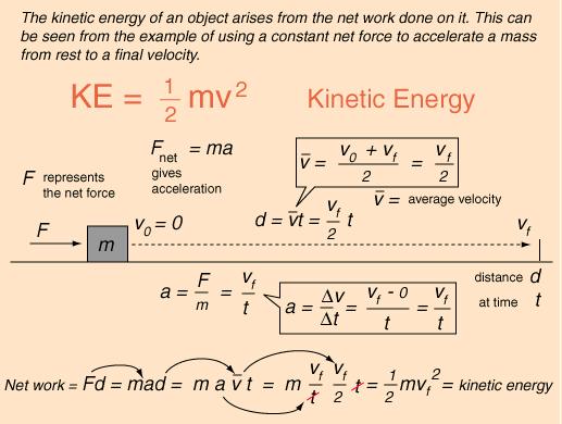
Kinetic Energy (KE)
Elevation (Potential) Energy (EE)
Continuity Equation
Volume
Flow Rate in must equal Volume Flow rate out.
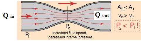
Qin = Qout
Q = A x V
A1 x V1 = A2 x V2
V2 = (A1 x V1) / A2
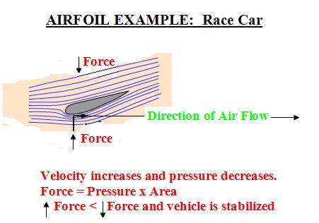
Bernoulli's Principle
When
the velocity of a fluid increases, the pressure exerted by that fluid decreases.
Curve of a Baseball Example
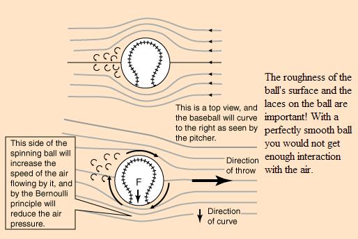
For an animation of why curve balls curve, click here
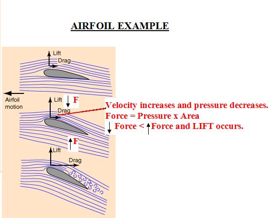
To view an animated air foil example, click here.Demo:: Take a sheet of paper, and tear a strip (approximately 1 1/2 inches x 11 inches)
Hold the paper strip under your bottom lip (lenghtwise facing from you).
Blow across the top of the strip of paper....what happens? Why?ROLLING CANS DEMO
FLOW THROUGH CONDUITS (PIPES, TUBING, HOSE)
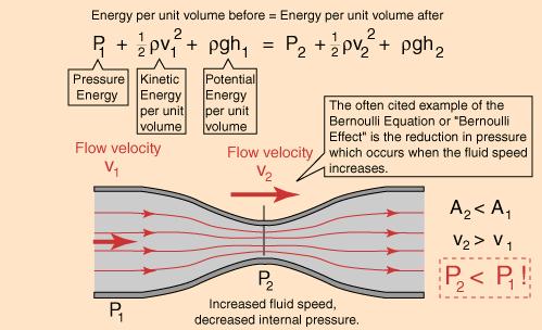
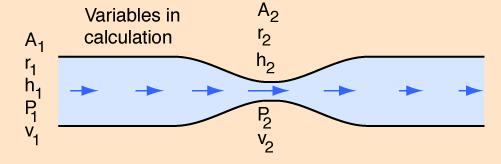
Where:
A = Area
r = Radius
h = height or Elevation
P = Pressure
v = Velocity
Venturi Demo
Flow Example 1 : http://library.thinkquest.org/27948/bernoulli.html
Flow Example 2 (with Q,V,A plot: http://home.earthlink.net/~mmc1919/venturi.html#animation

Darcy's Equation
Pressure losses through fluid systems
WEEK 12 CONDUCTORS AND SIZING
Piping Selection Chart: http://www.onlinepipe.com/pipechart.html
Flexile Hose Types :http://www.hydraulicspneumatics.com/200/TechZone/HydraulicHoseTu/Article/True/6417/TechZone-HydraulicHoseTu
Flexible
Hose Sizes and Pressure Ratings (SAE)
Fundamentals of Pneumatics (tutorial
with video clips)
http://www.nfpa.com/Training-Pneumatic/
KEY EQUATIONS:
(P1V1)/T1 = (P2V2)/T2
CONSUMPTION RATES: CR = (atmospheric
pressure + gage pressure) / atmospheric pressure; Based on standard air,
atmospheric pressure is assumed to be 14.7 pisa for the English System,
101 KPa for the Metric System.
CR = (14.7 + gage pressure) / 14.7
Qr(cyliner) = (A x S x N x CR) / K Note: In the English System: A= in sq. S = in. N=cpm ; CR=compression rate; K = 1728
Qr (cylinder) = (A x S x N X CR)/ 1728
Qr(motor) = (Vd x N x CR) / K ; Note In the English system: Vd in cubed / rev; N = rpm; CR = compresstion ration; K = 1728
Qr(motor) = (Vd x N x CR) / 1728
SIZING RECEIVERS: (an example problem is also shown in your text)
Vr
= atmospheric pressure x (t) x (Qr-Qc) / (Pmax - Pmin)
t is the time the system is consuming air (usually the maximum
flow condition);
For the English system, using standard air and SCFM for Q the equation
is as follows:
Vr = [14.7 x (time in minutes) x (Qr - Qc)] / [ PSI(max) - PSI(min) ]
PRESSURE LOSSES DUE TO FRICTION: ( English System - assuming schedule 40, commercial steel pipe)
General equation for Delta P = c x L x Q2 / CR x d5
Specifically for commercial steel pipe, schedule 40, English system only.
Delta P = (0.1025 x L x Q2) / ( 3600 x CR x d 5. 31 )
Where 0.1025 = friction factor for commercial steel pipe (these coefficients
are experimentally derived
based on the type of conduit being used.
L = Total length of pipe + equivalent lenght for valves and fittings.
Q = flow in SCFM
3600 = Constant to convert units
CR = Compression ratio
d = pipe diameter in inches (use actual inside diameter for schedule 40
pipe).
POWER AND HORSE POWER (For adiabatic conditions which assumes no loss or gain of heat).
To determine the horsepower and power required to drive an air compressor, the following formulae can be used:
For the English System, Use:
HP = [ (Pin x Q) / (65.4)] x [ (Pout / Pin)0.286 - 1 ]
Where: Pin = inlet
atmospheric pressure ( psia)
Pout = outlet pressure (psia)
Q = Flow rate (standard cubic feet per minute)
Note: This is a variation of the formula used in the Norvelle text.
The 0.0286 constant is for air under adiabatic conditions.
for an explanation of the adiabatic process click
HERE
For the metric System to determine theoretical power (kW) use:
Power (kW) = [ (Pin x Q) / 17.1 ] x [ ( Pout / Pin) 0.286) - 1 ]
Where: Pin = inlet atmospheric pressure (kPa abs)
Pout = outlet pressure (kPa abs)
Q = flow rate (standard meters cubed per minute)
WEEK 15 FINAL EXAM
BACK INDEX PAGE