PURPOSE
This laboratory assignment will introduce
students to Automation Studio software and provide an opportunity
to observe the relationships between Force (F), Pressure (P), Area
(A)
and Flow rate (Q), Velocity (V), and Area (A) in a simple linear
hydraulic circuit. The bore and rod diameter for a
2:1 area ratio will first be determined for the given system pressure
and required force. Next, the required pump size will be
determine to obtain a cycle time of 12 seconds for the same circuit.
OBJECTIVES
After completing this laboratory, you should be able to do the following:
1. Determine the purpose and function of basic components in a simple linear hydraulic circuit;This laboratory evaluates two basic relationships in a basic linear circuit including Pascal's Law and factors affecting speed of an actuator.2. Identify ISO symbols and circuit components ;
3. Develop a working hydraulic schematic in Automation Studio;
4. Conduct a computer simulation of circuit operation;
5. Observe pressure differences (extending vs. retracting);
6. Determine the appropriate actuator size for bore and rod diameter assuming a 2:1 area ratio;
7. Determine the appropriate pump size in Liters Per Minute (LMP) to drive the hydraulic cylinder achieving a 12 second cycle time.
8. develop a concise technical laboratory report of your findings.
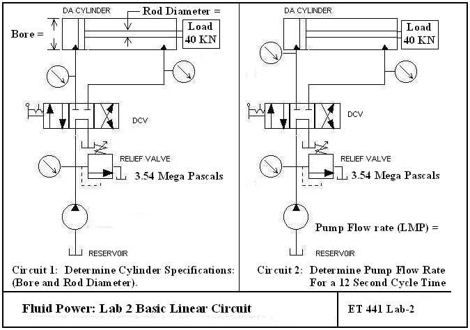
CIRCUITSComponents Required: Computer running Automation Studio; Unidirectional, fixed displacement hydraulic pump with reservoir; Relief Valve: Set relief valve to 500 psi. Directional Control Valve (4 way, 3 position, tandem center) Pressure gages Linear Actuator (specifications to be determined).
PROCEDURE: The following steps should be
taken in carrying out the execution of laboratory one. Take care
to follow
procedures as demonstrated by the instructor when constructing the
circuits in Automation Studio.
____ 1. Construct circuit one as show above in Automation Studio.
____ 2. Manually Calculate the required cylinder BORE and ROD DIAMETER; Record the calculated values in the chart below.
____ 3. Enter the calculated cylinder
parameters (cylinder bore and rod diameter) in Automation Studio by
clicking on the DA cylinder icon.
____ 4. Assume no inertia or friction for the actuator by entering 0 for each of the cylinder parameters.
____ 5. Adjust the relief valve for a minimum of 3.54 mega pascals.
____ 6. Run a simulation of the circuit,
check and record pressure during extension. (Note: The
loading conditions are assumed to be
during extension only. You must remove the load by setting it to
zero during retraction to accurately simulate pressures in the system).
Do this, and record the pressure during retraction.
____ 7. Assuming a required total cycle time
of 12 seconds, calculate the required pump flow rate in Liters Per
Minute (LPM) assuming a stroke of 1200 mm.
Enter the calculated values in the chart shown below.
____ 8. Complete calculations for velocity during extension and retraction; Enter values in the chart below.
____ 9. Note: Automation cannot
accurate simulate time of extension and retraction due to differences
in processor speeds of various computers used.
____10. Analyze your calculated and observed data.
____11. Using
the format shown in the lab report guide, submit a formal written
lab report
by next class meeting or as requested by your lab instructor.
RESULTS (Example charts, create your own in Excel).
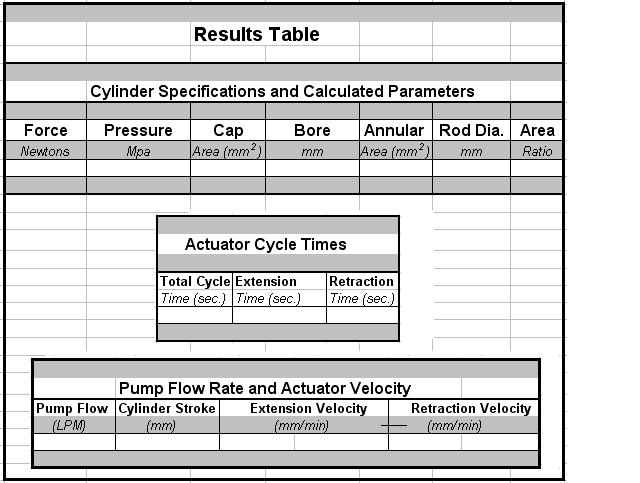
Cylinder Specifications Calculations:
Actuator Time Calculations:
Pump Flow Rate and Actuator Velocity Calculations: