PURPOSE
The purpose of the lab is provide an
application for system design, AND to serve as a review for test
one. System specifications for an apple juice
processing work cell will be studied. This lab will cover
most of the topics presented thus far in the class, and students
will determine design parameters for actuators, hydraulic fluid,
power, horsepower, and cost to operate the work cell.
SYSTEM
OPERATION
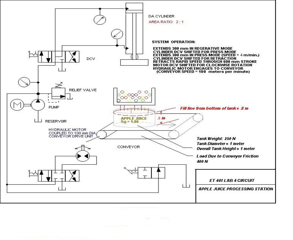
A linear hydraulic circuit will be specified for pressing apples into juice, and a rotary circuit for powering a conveyor. The hydraulic circuit consists of two actuators including a double acting cylinder for press application and a hydraulic motor for driving a conveyor This system is assumed to be operated manually using directional valves as indicated in the system schematic. The operator positions the juice on the conveyor under the press by shifting the Directional Control Valve (DCV) associated with the hydraulic motor driving the conveyor Once the container is in position, the hydraulic cylinder is activated in regenerative mode during the first half of extension The operator will then shift the cylinder DCV to activate the press (feed) mode for the last half of the extension cycle. Upon reaching full extension, the operator retracts the cylinder, and the cycle repeats until enough juice has been produced to fill the container to the fill line as indicated on the schematic The conveyor will be activated by the operator to dump the container then reposition the container to allow for the entire cycle to be repeated..
OBJECTIVES
After completing this laboratory, you should be able to do the following:
1. Determine the purpose and function of basic components in a simple linear and rotary hydraulic circuit;This laboratory incorporates two different hydraulic circuits in a basic system. A required load of 100 kN (including friction) must be produced by the cylinder during the "press" portion of the cycle. The load requirements of the hydraulic motor will be determined from the volume and weight density of fluid being processed. Frictional loads will be assumed as specified on the system schematic as shown below.2. Identify ISO symbols and circuit components ;
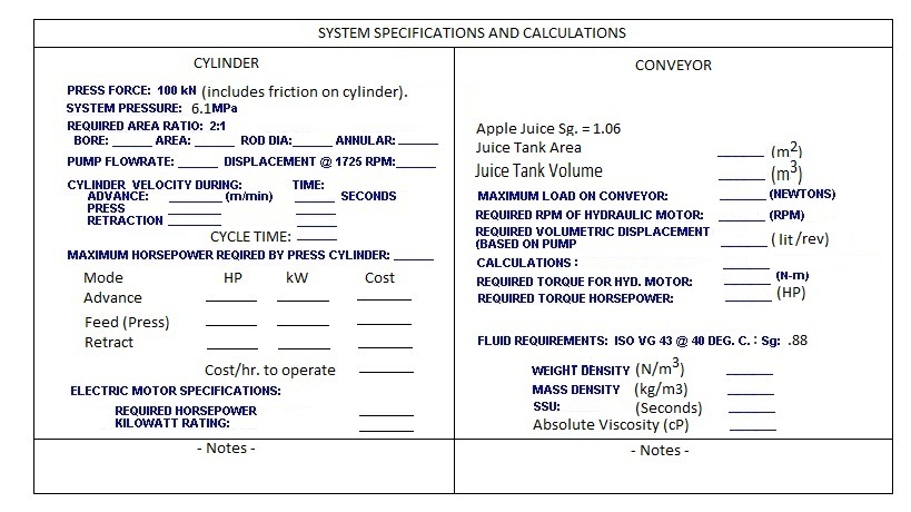
3. Determine cylinder specifications for area, bore, cycle time, and horsepower;
4. Determine hydraulic motor specifications for load, rpm, displacement, torque, and horsepower;
5. Determine prime mover specifications for rated horsepower and kilowatt rating, and cost of system operation;
6. Determine fluid specifications weight density, mass density, viscosity.
Components Required:
CIRCUITUnidirectional, fixed displacement hydraulic pump with reservoir; Relief Valve Set to 6.1 MPa NOTE: A PRESSURE DROP OF .4 MPa is assumed from the relief valve to the A port AND the B port of the cylinder.
Therefore a maximum of 5.7 MPa is available at the cylinder. The following pressures are assumed (at the cylinder)
during the three phases of operation for the hydraulic cylinder:
1. Advance (Regenerative Mode) P = 2.5 MPa
2. Feed (Press Mode): P = 5.7 MPa
3. Retract Mode: P = 1.7 MPa
Directional Control Valves (4 way, 3 position(2) AND 2 port , two position (1);
Pressure gauges; Double acting, differential linear actuator (hydraulic press cylinder); Rotary Actuator (hydraulic motor to drive conveyor); NOTE: ASSUME PUMP EFFICIENCY IS 85% AND ELECTRIC MOTOR EFFICIENCY IS 90%.
PROCEDURE
____ 1. Complete the calculations and
determine the specifications as indicated below:
____ 2. Study the circuit as shown in the
system schematic diagram, and identify the schematic symbol for
each hydraulic component. Make sure you understand how the
system
operates and how fluid flows throughout the circuit during
operation. It is highly recommended that you build the
circuit in Automation Studio and observe the operation;
____ 3. Identify the function of each
component;
____ 4. Reference your textbook for find sources from the web relating to ISO VG 43 hydraulic fluid.
____ 5. Note: The circuit has been simulated to verify operation.
____ 6. Use the results of this lab as a study guide for test one.
____ 7. NOTE: A formal
write up is required (same standard format) including all
calculations and completion of the above
specifications.
Include
a summary table for all specifications, and attach an appendix
showing
ALL REQUIRED calculations neatly labeled by category. The
report will be due next Tuesday
(Thursday for ET 441-50) of next week.