PURPOSE
This laboratory assignment will provide an opportunity
to observe the relationships between Force (F), Pressure (P) and Area (A)
in two simple linear hydraulic circuits. Pressure will
be compared for two actuators under the same loading conditions.
Therefore, Force (F) will remain constant. The purpose is to determine
the effect of changing the size of cylinder in a hydraulic circuit.
OBJECTIVES
After completing this laboratory, you should be able to do the following:
1. Determine the purpose and function of basic components in a simple linear hydraulic circuit;This laboratory incorporates two different hydraulic cylinders in a basic linear circuit. The load will be held constant on the cylinders during extension and retractiion. If force remains constant, then pressure should change as the effective piston area changes. This relationship is based on Pascal's Law.2. Identify ISO symbols and circuit components ;
3. Develop a working hydraulic schematic;
4. Conduct a computer simulation of circuit operation;
5. Observe pressure differences (extending vs. retracting);
6. Observe pressure differences between two cylinders;
7. Determine the area ratio and force ratio of two hydraulic cylinders.
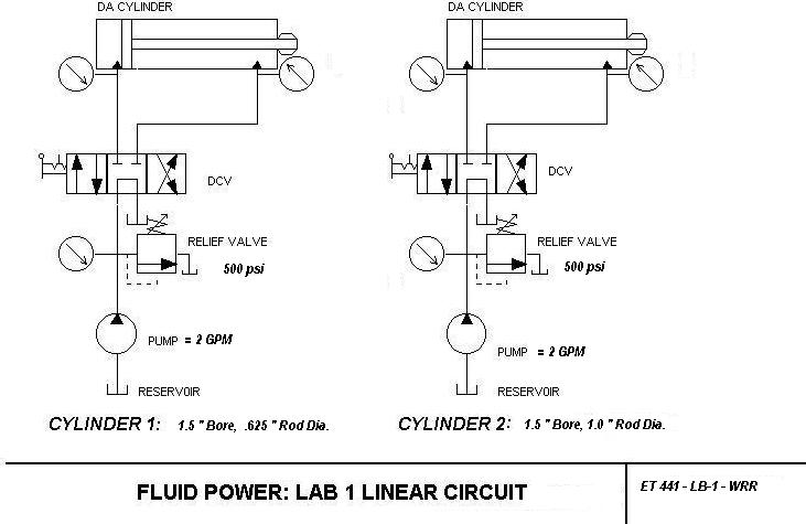
CIRCUITComponents Required: Vickers Industrial Hydraulic Trainer; Unidirectional, fixed displacement hydraulic pump with reservoir; Relief Valve: Set relief valve to 500 psi. Directional Control Valve (4 way, 3 position, tandem center) Pressure gages; Linear Actuator (1.5 inch bore, 5/8 inch rod); Linear Actuator (3.0 inch bore, 1.25 inch rod).
CYLINDER 1
CYLINDER 2
PROCEDURE: The following steps should be
taken in carrying out the execution of laboratory one. Take care
to follow
procedures as written, and always observed the safety rules. Always
assume a system is under full presure,
and take measures to relieve pressure before connection or disconnecting
hoses.
____ 1. Construct the circuits as show above on the
Vickers hydraulic trainer.
____ 2. Identify the function of each component;
____ 3. Define the standard color codes used to represent
the state of fluid in a system
(show legend on your schematic);
____ 4. Identify the name and number of each component
by generating a schedule on
your schematic (required for written report) ;
____ 5. Adjust the relief valve to 500 psi; Note: Flow rate for this circuit is 2 GPM;
____ 6. Complete all connections for the basic circuit using the 1.5 inch bore, .625 rod cylinder;
____ 7. Turn on the trainer and Shift the DCV for extension;
____ 8. Extend and retract 1.5 inch bore, 5/8 inch
rod clyinder and record the pressure readings
(while the actuator is in motion);
____ 9. Observe and record the pressure during extension
and retraction;
____10. Extend and retract the 1.5 inch bore, 1.25
inch rod cylinder;
____11. Observe and record the pressure during extension and retracton;
____12. Record all pressure readings on the chart shown below:
____ 13. Calculate the cap and annular area for each of the cylinders and record
____14. Calculate the theoretical pressure ratio during extension and retraction for each cylinder;
____ 15. Compare observed values to theoretical pressures.
____ 16. Determine experimental error;
____ 17. Using
the format shown in the lab report guide, submit a formal written
lab report
by next class meeting or as requested by your lab instructor.
RESULTS
| ACTUATOR | BORE | ROD DIAMETER | CAP AREA | ANNULAR AREA |
| CYLINDER 1 | 1.5 INCHES | .625 INCHES | ||
| CYLINDER 2 | 3.0 INCHES | 1.25 INCH |
| ACTUATOR | PRESSURE EXTENDING | PRESSURE RETRACTING | PRESSURE IN NEUTRAL |
| CYLINDER 1 | |||
| CYLINDER 2 |
2. What is the maximum pressure of the system and why? ________________________________________________
_______________________________________________________________________________________
3. Is there any difference in pressure during extensioncompared
to retraction for cylinder 1?
______ for cylinder
2 ? ____.
Explain _______________________________________________________________________________
_______________________________________________________________________________.
4. Is there any difference in pressure during retraction for cylinder 1 compared to cylinder 2? _______.
Explain. _______________________________________________________________________________
_______________________________________________________________________________.
5. Is there any difference in pressure during extension for cylinder 12 compared to cylinder 13? _______.
Explain. _______________________________________________________________________________
_______________________________________________________________________________.
6. Would the pressure readings you observed in the
simulation be consistant with actual pressure
readings on a
"live" system?
Explain________________________________________________________________________
________________________________________________________________________________