PURPOSE: This laboratory exercise is a continuation of LAB 5. The purpose will be to controlLAB 6: STEPPER MOTOR CONTROL
USING AN OPERATOR INTERFACE
OBJECTIVE: The main objective of
this laboratory is implementing a TD 200 unit to provide the
following:
1. Initiate the starting of the stepper motor sequence.
2. Display direction of the stepper motor.
3. Display the angular position of the stepper motor shaft.
PROCEDURE: Modify the program developed in lab 5 to accommodate the following.
1. Define 4 data bytes
corresponding to the required step sequence bit pattern;
Change your program so that VB 200, VB210, VB 220, VB 230 and
VB240
are used for stop, step1, step 2, step 3, and step 4 respectively.
2. Create a start condition using F1 on the TD 200 ( M0.0)
3. Create a stop condition using F2 on the TD 200 (M0.1)
4. Create data blocks
for performing the following functions:
a. Display: PRESS F1 TO START F2 TO STOP (for system
control)
a. Display : DIR: CW (when stepper motor is running cw);
b. Display: DIR: CCW (when stepper motor is running ccw);
c. Display DEG: XX.XX (to display the calculated
angular position in degrees).
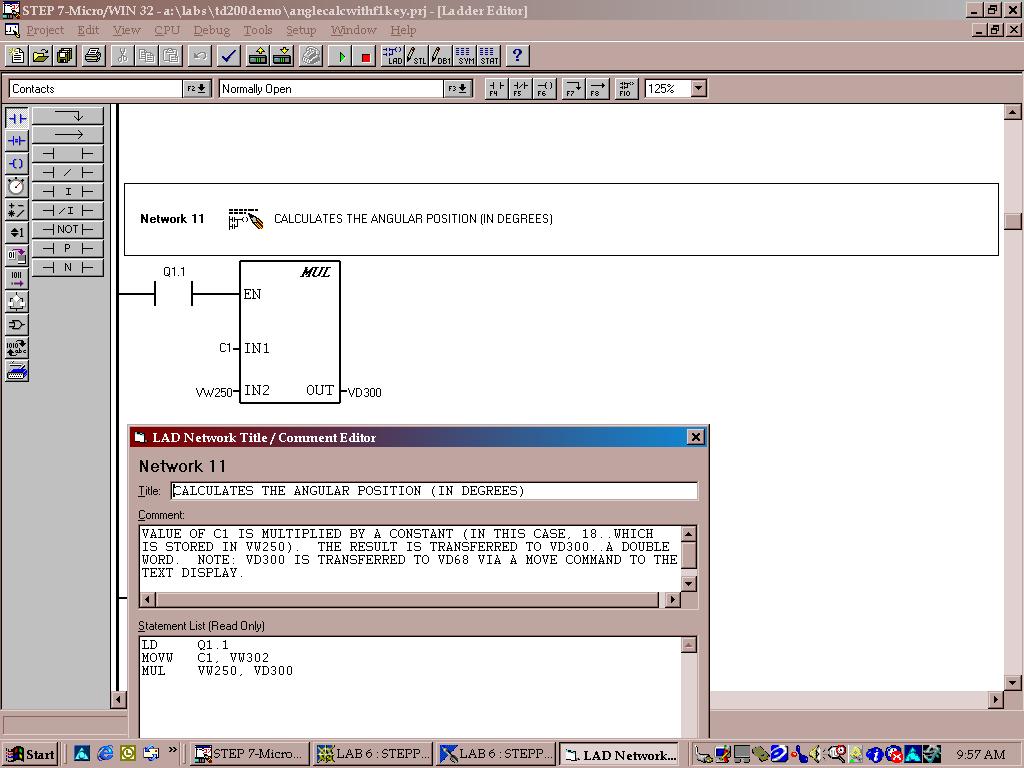
5. Use the MULTIPLY function
to multiply the contents of C1 by 1.8 degrees.
(This value will be moved to a data block to show the angular position).
(NOTE: USE DATA BLOCK VW250 TO STORE THE NUMBER 18...e.g. VW250
18)
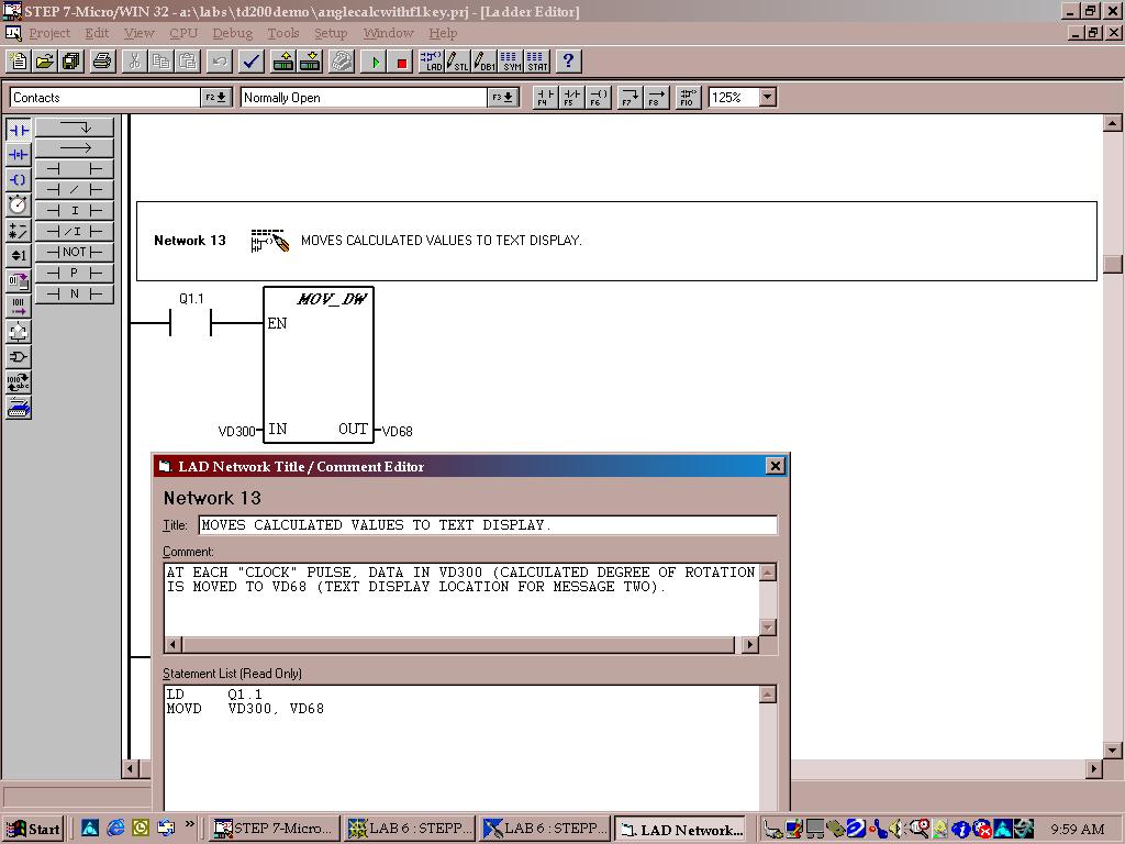
EXAMPLE:
EXAMPLE SHOWING MOVE STATEMENT TO TRANSFER "ANGULAR DEGREES" TO
VD68 CORRESPONDING TO TEXT DISPLAY MESSAGE:
6.
Use Q Byte (QB0) as the output BYTE for controlling the motor;
7.
Program an on delay timer to create a one shot "clock pulse" from a counter
at a time interval
of 10 milliseconds;
8.
Use one counter to count step sequences and a second counter to count total
sequences;
9.
Use the Move Byte function to move the required data byte to QB0 depending
on the
counter value being used to count step sequences.
10. Write the
program to generate the pulse train required for one CW rotation, two CCW
rotations, and one CW rotation.
11. Compare the
finish point to the original starting point on the motor shaft and determine
if any error occurs (e.g. too few or to many steps generated).
12. Modify your program
to compensate for any error (if required) and be prepared to
explain why any modification was necessary.
13. Submit a written
laboratory report, following the usual format.
The following four step in put sequence provides CW rotation as viewed
from then nameplate end
of the motor. To reverse the direction, step sequence is 1,4,3,2,1.
STEP SWITCH 1
SWITCH 2 SWITCH 3
SWITCH 4
1
ON
OFF
ON
OFF
2
ON
OFF
OFF
ON
3
OFF
ON
OFF
ON
4
OFF
ON
ON
OFF
1
ON
OFF
ON
OFF
SUPPLEMENTAL SUPPORTING DIAGRAMS
AND EXAMPLES
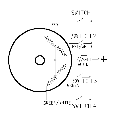
WIRING DIAGRAM
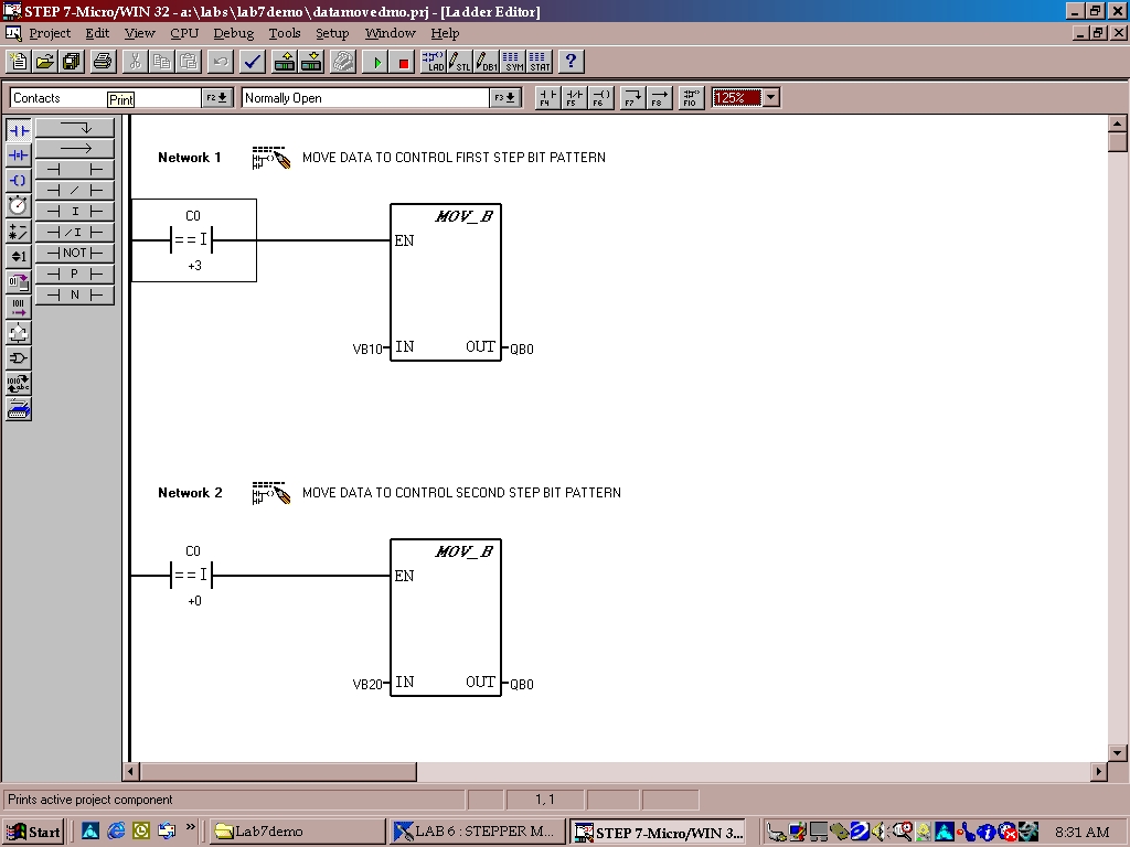
MOVE FUNCTIONS
EXAMPLE OF USING COUNTER WITH IF CONDITION (----| = = I |-----)
TO MOVE DATA
FROM A VARIABLE BYTE (VB10) TO OUTPUT BYTE (QB0).
NOTE: IF COUNTER 0 (C0) IS EQUAL TO 3, THEN THE CONTENTS
OF VB10 WILL BE
MOVED TO OUTPUT BYTE (QB0) AS SHOWN IN NETWORK 1 BELOW.
Description of operation: MOV_B
The Move Byte (MOV_B) box moves the input byte (IN) to the output byte
(OUT). The input byte is not altered by the move.
Operands:
IN (byte): VB, IB, QB, MB, SMB, SB, AC, Constant, *VD, *AC
OUT (byte): VB, IB, QB, MB, SMB, SB, AC, *VD, *AC
Description of operation:
DATA BLOCKS: YOU WILL NEED TO CREATE DATA BLOCKS TO STORE
THE CONTENTS OF
THE BIT PATTERNS REQUIRED TO INDEX THE STEPPER MOTOR. ONE BLOCK
WILL BE REQUIRED
FOR EACH BIT PATTERN AS SHOWN BELOW:
//
//DATA BLOCK TITLE COMMENTS
//
//Press F1 for help and example data block
//
VB200 0 // DATA
FOR TURNING MOTOR COILS OFF (BINARY 0000)
VB210 10 // DATA
FOR FIRST STEP SEQUENCE (BINARY 1010)
VB220 9 // DATA
FOR SECOND STEP SEQUENCE (BINARY 1001)
VB230 5 // DATA
FOR THIRD STEP SEQUENCE (BINARY 0101)
VB240 6 // DATA
FOR FOURTH STEP SEQUENCE (BINARY 0110)