BASIC STEPPER MOTOR CONTROL USING A PLC
PURPOSE: The purpose of this laboratory exercise is to
control the direction and speed of
a stepper motor using a PLC. Data Bytes will be used to define
the sequence bit pattern
for each respective step. Speed of the motor will be controlled
using a timer for delaying
between pulse output. Counters will be used to keep track
of the number of bit patterns produced
and the total steps generated
in both the forward and reverse direction.
OBJECTIVE: Write a PLC program to drive the pointer on the simplified measuring device
to 10 mm greater than the starting location, and then return to the original starting
point.
PROCEDURE: The following steps should be taken to carry out this laboratory exercise:
1. Define 4 data bytes corresponding to the
required step sequence bit pattern;
2. Use Q Byte (QB0) as the output BYTE
for controlling the motor;
3. Program an on delay timer to create a one
shot "clock pulse" from a counter at a time interval
of 20 milliseconds;
4. Use one counter to count step sequences
and a second counter to count total sequences;
5. Use the Move Byte function to move the
required data byte to QB0 depending on the
counter value being
used to count step sequences.
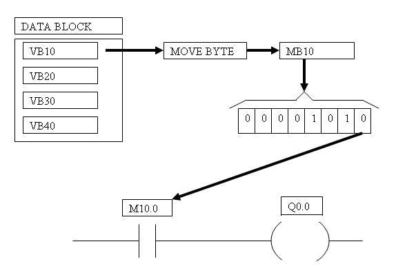
Note: An improvment in your program can be made by following the following method.
By using Memory Bytes (MB....i.e. MB10) rather than QB0, extra output bits can be reserved for
controlling outputs rather than the four field coils for the stepper motor.. Remember a BYTE = 8 bits, and
QB0 will consume all 8 bits of the output byte for addresses Q0.0 through Q0.7. Since only 4 bits
are actually required for controlling the stepper motor, 4 bits of QB0 would be "wasted". Therefore
to avoid this, simply MOVE the DATA BYTES (i.e. VB10 to MB10), then use discrete individual
bytes of MB10 to control the field coils of the stepper motor. A conceptual diagram and example
PLC Networks are shown below:
6. Write the program to generate the pulse
train required for the distance to be moved.
(Note: You will have
to determine the total number of revolutions required to equate to 10
mm).
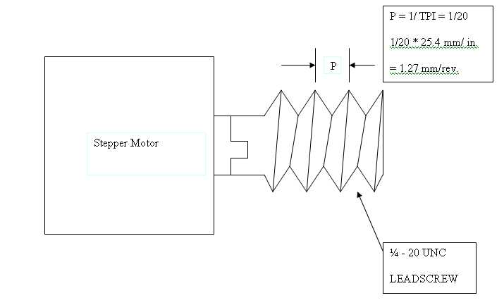
The leadscrew attached
to the stepper motor is 1/4-20 UNC, and is a single thread.
Therefore, the lead is equal to the pitch = 1/20 inch per revolution.
!/20 in. X 25.4 mm/in. = 1.27 mm/rev.
7. Complete your PLC program and download to the simplified measuring station; run the PLC program.
8. Compare the finish point to the original
starting point on the motor shaft and determine
if any error occurs
(e.g. too few or to many steps generated).
9. Modify your program to compensate for any
error (if required) and be prepared to
explain why any modification
was necessary.
10.Submit a written laboratory report, following
the usual format.
SUPPLEMENTAL INFORMATION
The following four step in put sequence provides CW rotation as viewed
from then nameplate end
of the motor. To reverse the direction, step sequence is 1,4,3,2,1.
STEP SWITCH 1
SWITCH 2 SWITCH 3
SWITCH 4
1
ON
OFF
ON
OFF
2
ON
OFF
OFF
ON
3
OFF
ON
OFF
ON
4
OFF
ON
ON
OFF
1
ON
OFF
ON
OFF
SUPPLEMENTAL SUPPORTING DIAGRAMS
AND EXAMPLES
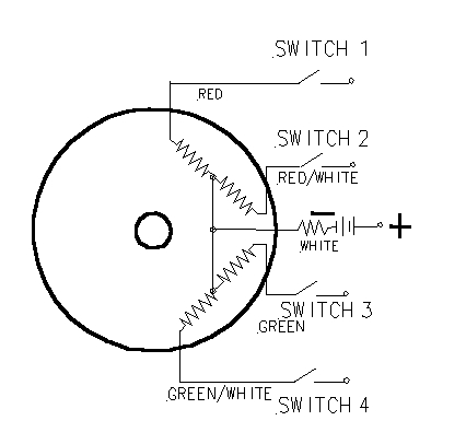
WIRING DIAGRAM
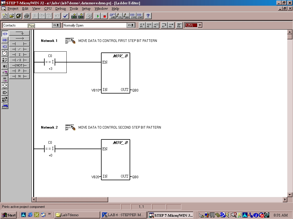
MOVE FUNCTIONS
EXAMPLE OF USING COUNTER WITH IF CONDITION (----| = = I |-----)
TO MOVE DATA
FROM A VARIABLE BYTE (VB10) TO OUTPUT BYTE (QB0).
NOTE: IF COUNTER 0 (C0) IS EQUAL TO 3, THEN THE CONTENTS
OF VB10 WILL BE
MOVED TO OUTPUT BYTE (QB0) AS SHOWN IN NETWORK 1 BELOW.
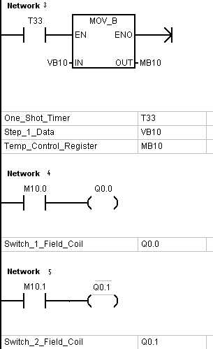
Description of operation: MOV_B
The Move Byte (MOV_B) box moves the input byte (IN) to the output byte
(OUT). The input byte is not altered by the move.
Operands:
IN (byte): VB, IB, QB, MB, SMB, SB, AC, Constant, *VD, *AC
OUT (byte): VB, IB, QB, MB, SMB, SB, AC, *VD, *AC
Description of operation:
DATA BLOCKS: YOU WILL NEED TO CREATE DATA BLOCKS TO STORE
THE CONTENTS OF
THE BIT PATTERNS REQUIRED TO INDEX THE STEPPER MOTOR. ONE BLOCK
WILL BE REQUIRED
FOR EACH BIT PATTERN AS SHOWN BELOW:
//
//DATA BLOCK TITLE COMMENTS
//
//Press F1 for help and example data block
//
VB10 10 // DATA FOR FIRST STEP SEQUENCE
(BINARY 1010)
VB20 9 // DATA FOR SECOND STEP SEQUENCE (BINARY
1001)
VB30 5 // DATA FOR THIRD STEP SEQUENCE
(BINARY 0101)
VB40 6 // DATA FOR FOURTH STEP SEQUENCE (BINARY
0110)