PURPOSE:
The purpose of this laboratory is to develop an
understanding of how shift registers work and can
be applied to control a tracking system.
Parts are inspected in Zone 1 and "tracked" through the
processing line until Zone 5 is reached.
If a bad part is present at Zone 5, it is diverted off of the conveyor
upon activation of a diverting solenoid gate.
Good parts continue downstream.
OBJECTIVES:
After completion of this laboratory exercise you should be able to do the following:
1. Explain the theory
of how a shift register works;
2. Program a shift register
into the S7224 OR 214 PLC;
3. Address individual
bits in the shift register;
4. Implement a data
bit for storing "inspection" status;
5. Use individual register
bits to control discrete outputs;
6. Develop a "one shot"
pulsed input to control the shifting of bits;
7. Program counters
to keep track of good parts, bad parts, total parts;
8. Monitor the status
of the plc using a status table.
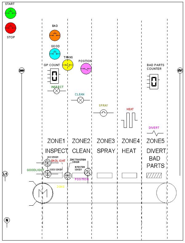
SYSTEM OPERATION
The system is activated by depressing the start
switch which turns on the conveyor motor. Parts are
equally spaced by a flexible locating fixture
on the conveyor. Parts
entering the system at Zone 1 one
are inspected as good (short) or tall (bad) using
an optical switch. A counter keeps track of the total
number of parts inspected. As the parts
move between zones a third optical sensor is used to shift the
data bit stored in the shift register at
position one (indicating good or bad part: 1 = bad, 0 = good).
If a good part is detected, processing
occurs at each successive zone. However if a bad part is
detected, processing is suspended as the
bad part is tracked to Zone 5. At this station, bad parts are
diverted off the conveyor and good parts continue
downstream. A second counter keeps track of the
number of bad parts leaving the system.
Parts are equally spaced on the conveyor and "in position"
is detected by an optical sensor within Zone
2.
REQUIREMENTS:
Develop the control logic for the system described.
Your program should be able to do the following:
1. Activate
the system when the start switch is depressed
2. Detected
good or bad parts at Zone 1;
3. Detect
"in position" at Zone 2;
4. Turn
on a spray nozzle solenoid at Zone 3 ONLY IF A GOOD PART IS PRESENT;
5. Turn
on a heat element at Zone 4 ONLY IF A GOOD PART IS PRESENT;
6. Track
bad parts through the system;
7. Divert
bad parts off the conveyor by activating a solenoid diverter at Zone 5
if a bad part is present;
8. Count
the number of bad parts;
9. Count
the number of good parts;
10. Count the total
number of parts.
11. Shut down the system
anytime the stop switch is depressed.
Note: DEVELOP THE CONTROL LOGIC FOR THE SIEMENS 224/214 PLC in MicroWin32.
Follow the usual format for documenting the laboratory exercise.