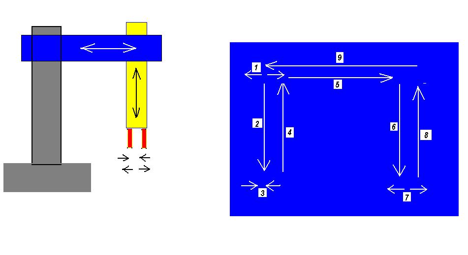
Pick-and-Place Robot Diagram showing required sequential moves
PURPOSE:
The purpose of this laboratory exercise is to control a pneumatic pick-and-place
robot using ladder logic.
Automation Studio will be used to simulate the pneumatic system, and
the
AB-PLC simulator will be
used to develop control logic.
OBJECTIVE: After completing this laboratory exercise, you should be able to do the following:
1. Write a control sequence matrix describing the conditions and
restriction of operations;
2. Simulate the circuit in Automation Studio and document the
step-by-step operation;
3. Write an Allen-Bradley Simulated PLC program
4. Label all electrical inputs and outputs by name and function;
5. Write a detailed operational procedure for the system.
REQUIRED CIRCUIT OPERATION:
Three pneumatic actuators provide motion control for a pick-and-place assembly
robot. A vertical cylinder provides up and down
motion while a horizontal cylinder provides left to right motion.
Grip and release control is provided by a third pneumatic actuator.
The robot waits for a start signal, then executes the operations as shown
below. At the end of the assembly cycle, a finish signal is
transmitted.
1. Wait for start signal; Upon start continue (gripper
open)
2. Extend vertical cylinder
3. Grip part
4. Retract vertical cylinder
5. Extend horizontal cylinder
6. Extend vertical cylinder
7. Release part
8. Retract vertical cylinder
9. Retract horizontal cylinder
10. Send end of cycle (finish) output signal
11. Count the total number of cycles.
Pick-and-Place
Robot
Diagram showing required sequential moves
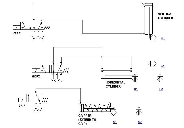
Pneumatic System:
PROCEDURE:
1. Develop a control matrix for the system shown;
2. Create the pneumatic circuit in Automation Studio;
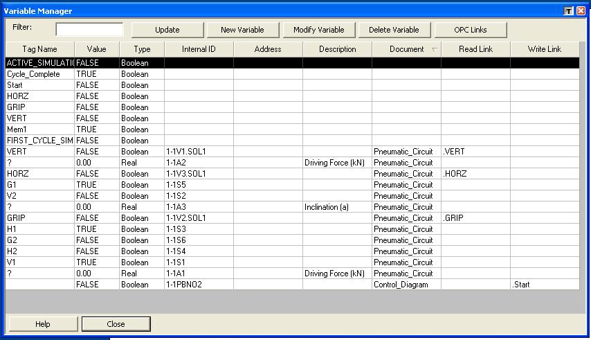
3. Draw the electrical control circuit AB PLC simulator and create
appropriate tags
(sample chart shown below);
4. Simulate the circuit to verify the operation of the clamp and
work sequence;
5. Simulate the circuit in Step-By-Step mode and note the change
of states of electrical components;
6. Write a heading for each rung, indicating the control function
of each;
7. Label each electrical component in the ladder diagram;
8. Describe the function within each rung;
9. Write a detailed operational sequence for the system. Provide
a detailed, step by step description
of the electrical control circuit, rung by rung.
10. Submit a formal written report.