Lab 2A: PLC Program Development for A Pneumatic Can Crusher
Abstract
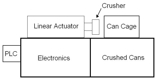
The pneumatic can crusher located in Belk 171 Automation Laboratory on the Western Carolina University campus was developed by Johnson Busick and Brett Banther. It was designed and built with the intent to be used as a laboratory exercise for the ET-472 Automation curriculum to demonstrate how pneumatic devices can be controlled via programmable logic controllers. The general structure of the device has a 24inch x 7inch footprint and utilizes two separate chambers designated for electronics and the generated crushed cans. The chamber housing the electronics is completely sealed off through the use of 3/16 clear acrylic sheet. This allows students to see the electronics but not have the ability to alter them in any way. The chamber for the aluminum cans is also sealed using acrylic sheet; however, has a removable door to allow the operator to remove the crushed cans upon successful execution of the embedded program. The design intent is that when an operator depresses two momentary contact switches simultaneously the linear actuator will extend and crush a single 12oz aluminum can. The actuator will then retract allowing the newly crushed can to descend though a slot via gravity into a containment unit located beneath.
Basic System Diagram
Electronic Components
The primary hardware components consist of the following:
• Siemens 224 programmable logic controller
• pneumatic linear actuator
• logical gate solenoid valves (x2)
• proximity sensors (x2)
• momentary contact switches (x2)
• two stage key switch
• 24-volt auxiliary power supply
*Note – All inputs and outputs are normally open devices
Required System Operation
Before the system can be activated, a key must be inserted into the key switch to turn the machine on. A program can then be uploaded into the PLC. The PLC program should not allow for operation of the solenoid valves until the following criteria is met:
• A can must be in place (proximity sensor senses a can)
• The can cage door must be closed (proximity sensor detects the door
is closed)
• Two momentary contact switches must be depressed simultaneously
When all of the abovementioned criteria is met, the solenoid valve for extension of the actuator is to be activated. The crusher is to remain fully extended for three seconds to allow pressure to build before activating the solenoid to retract the actuator. The crushed can will then fall though a slot and into the receptacle containment unit below. The embedded counter counts how many cans have been crushed and is reset when the following conditions are met:
• The can cage is closed
• There is not a can in place
• The left momentary contact switch is true for five seconds
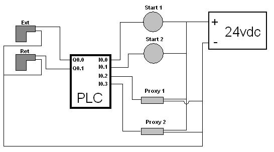
I/O Symbol Table
I0.0 – Left start switch
I0.1 – Right start switch
I0.2 – Proximity sensor for can
I0.3 – Proximity sensor for can cage
Q0.0 – Solenoid for extension phase
Q0.1 – Solenoid for retraction phase
Simplified Wiring Diagram
Requirements for Lab 2A:
Assume you have been contracted to develop a program for the system
described above. Write a PLC program along with all of the requirements for the simplified lab
format for write-up.