ET 472 FINAL EXAM
Purpose and System Operation
The purpose of this project
is to develop an inspection and processing system similar to the exercise
completed for laboratory number 2. However, for the final exam, LabVIEW will be
used rather than a PLC. The system
should inspect arriving parts for either short (good) or tall (bad) as they are
carried through the inspection portion of the system. After inspection, parts will pass through a
Zone Transition Sensor indicating that a part is present. If a good part is detected and the zone
transition sensor is activated, a logical one will be output for tracking. Similarly if a bad part is present and the
zone transition sensor is activated, a logical 0 will be the output for
tracking. If the zone transition sensor
is not activated, a logical 0 will also be the output indicating that no part
was physically detected on the conveyor system (this is the system
default).
Good Parts
When
good parts are processed through the system, a shift register will track the
parts inspection result and process at the downstream stations as follows: If a good part is detected, then the part
will been shown as good at the inspected parts station, and processed through
the clean, heat, and spray stations. The
divert station will be not be activated, thus allowing good parts to continue
straight through the system.
Bad Parts
When
bad parts are processed through the system, the shift register will track the
parts inspection result as a logical 0, transfer the bad parts through the
clean, heat, and spray stations (using no resources) until the divert station
is reached. At the divert station, parts
will be pushed off the system to a spur conveyor for sorting, reprocessing, or
scraping. Note: If no parts are present
on the system (the zone transition sensor is not activated) then the system
default will assume a bad part is present.
Requirements
The following requirements
must be met to obtain credit for the exam.
1. Complete a LabView Sub VI for the arrival and inspection
portion of the system. The Sub-VI should
process as shown in the system diagram and as demonstrated in class. Set the timing of the Sub-VI to 500 ms.
2. Create a LabView main VI to track the parts through
the system and control operations at downstream stations as described
above. The main VI should perform the
operations as shown in the diagram below and as demonstrated in class. Set the mail VI to run at 1 second.
3. Complete a written report in the same format as the
usual lab report. The report must
include the following:
a. Abstract 10
Points.
b. System requirements.
5 Points.
c. Symbols Chart
10 Points
d. Sequence Chart
15 Points
e. System Diagram
(Front Panel and Block Diagram)
30 Points
f.
Explanation of
system operation (in detail). 30 Points.
4.
NOTE: THE EXAM WILL BE DUE ON
EVENING OF THE EXAM. YOU MAY SUBMIT THE
EXAM EARLIER!
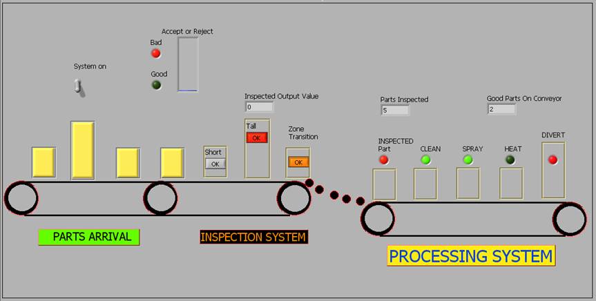
ET 472 FINAL PROJECT- EXAM SYSTEM
DIAGRAM