PROGRAMMING AND CONTROL OF A CLAMP
AND WORK SYSTEM USING AUTOMATION STUDIO AND
ALLEN-BRADELY PLC SIMULATOR
PURPOSE: The purpose of this laboratory exercise is to develop a simulated fluid power circuit and control method for a hydraulic press. Double solenoids will be used for each actuator. The required system operation is described below.OBJECTIVE: After completing this laboratory exercise, you should be able to do the following:
1. Develop a hydraulic circuit for the required system in Automation Studio;
2. Develop the required variables, tags and links for controlling the system;
3. Simulate the circuit in Automation Studio and document the step-by-step operation;
4. Write an Allen-Bradley Simulated PLC program to control the system as required
5. Simulate the circuit in Automation Studio and document the step-by-step operation;
6. Write a detailed operational procedure for the system.REQUIRED CIRCUIT OPERATION:
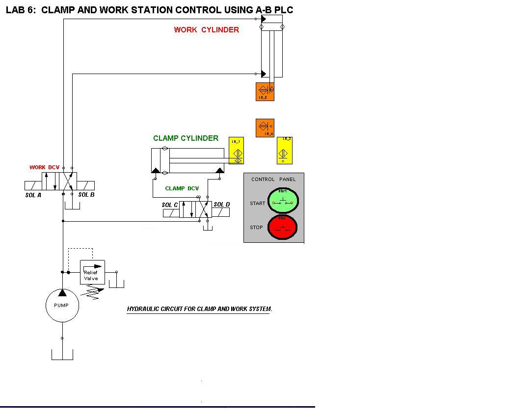
Two hydraulic cylinders are used in a work station. A horizontal cylinder is required to clamp and hold the part
during the work cycle. A second (vertical) cylinder is used to press a bushing into the housing of a pump. An adhesive
is applied to the bushing prior to the press mode, and 3 seconds set time is required under pressure. The sequence
of events are as follows:1. Wait for start signal; Upon start continue
2. Detect Part in place
3. Check for retraction of both cylinders
4. Extend clamp cylinder
5. Extend press cylinder and delay for 3 seconds
6. Retract press cylinder
7. Retract clamp cylinder
8. Send end of cycle (finish) output signal
9. Count the total number of cycles.PROCEDURE:
1. Develop a control matrix for the system shown below;
2. Create the following fluid circuit in Automation Studio;
3. Draw the PLC control circuit AB PLC simulator and create appropriate tags;
4. Simulate the circuit to verify the operation of the clamp and work sequence;
5. Simulate the circuit in Step-By-Step mode and note the change of states of electrical components;
6. Write a heading for each rung, indicating the control function of each;
7. Label each electrical component in the ladder diagram;
8. Describe the function within each rung;
9. Write a detailed operational sequence for the system. Provide a detailed, step by step description
of the electrical control circuit, rung by rung.
10. Submit a formal written report.