DYE PROCESSING SYSTEM USING SEQUENTIAL FLOW CHART  (SFC) PROGRAMMING

Purpose

The purpose of this laboratory exercise is to develop a control system for mixing a dye color used in paint processing.
Two pneumatic cylinders dispense concentrated colorants of red and blue to produce a WCU purple paint.  The formula is
two units of blue for every one unit of red.  The pneumatic system is shown if Figure 1.  Upon starting, the system should
activate a solenoid to allow a Directional Control Valve (DCV) to extend cylinder 2 (dispense blue colorant), delay for 3 seconds,
energize the retraction solenoid,  extend cylinder 2 a second time, delay for 1 second, energize the solenoid to extend cylinder 1
(dispense red colorant), then retract both cylinders.  Upon retraction of both cylinders, and a delay of 500ms, a counter should index
by one, delay for another 500ms, then display the counter value.   If the count value is less than a batch count of 5, the system will
activate an agitator, delay for 5 seconds then repeat  the entire process until a total batch count of 5 has been reached.  If the
count is equal to 5, then a "Batch Finished" light will be illuminated and the system waits for a RESET button to be depressed.
After the RESET button is depressed a reset light will illuminate, the counter will re reset to zero, and then start the sequence all
over from the beginning.

Objectives

After completing this laboratory exercise, you should be able to perform the following:

1.  Generate a control sequence diagram for the system.
2.  Develop the pneumatic schematic shown in Figure 1.
3.  Create an HMI control panel as shown in Figure 2.
4.  Create required tags for linking I/O in the control program.
5.  Develop a SFC control program.
6.  Simulate the system to verify the SFC program functions correctly.
7.  Develop a wiring diagram for PLC interface.
9.  Provide a documented SFC program listing.
9.  Complete a written report using standard format with a detailed explanation of how the system is controlled.

Keywords

SFC
Tags
Initial Step
Standard Step
Transition
Counter
Timer
AND Steps
OR Transitions


                                                 FIGURE 1:  PNEUMATIC CIRCUIT FOR DYE DISPENSING


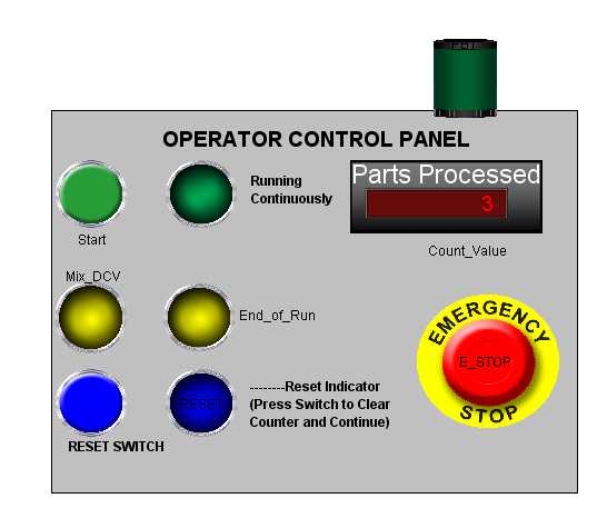
                                          FIGURE 2:   CONTROL PANEL LAYOUT

Pre-lab assignment

A demonstration will be given of a SFC program in class along with the procedure for developing a SFC
control program.  Study your notes, and be familiar with the SFC user's manual (available in the help menu in Automation Studio). 

Procedure

The following tasks should be completed in order to carry out this laboratory assignment:

1.  Study the system requirements, and develop a control sequence table of tasks.
2. Identify the required variables, and create the associated tags.
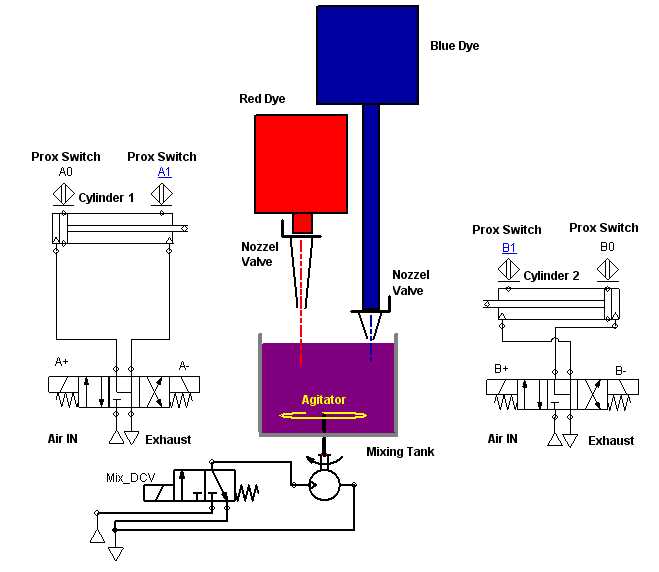
3.  Develop the pneumatic schematic shown in Figure 1.
4.  Create an HMI control panel as shown in Figure 2.
5.  Develop a SFC control program.
6.  Simulate the system to verify the SFC program functions correctly.
7.  Develop a wiring diagram for PLC interface.
8.  Provide a documented SFC program listing.
9.  Complete a written report using standard format with a detailed explanation of how the system is controlled.