
PURPOSE
The purpose of this module is to provide an introduction to selected control methods used at the machine/cell level for industrial automation. Two common methods of control in manufacturing systems are CNC controllers and Programmable Logic Controllers. This module will be divided into two section, dealing with these two types of controllers.
Section I - CNC Controllers
OBJECTIVES
The after completing this module, you should be able to do the following:
1. Explain the difference between open loop and closed loop systems;
2. Identify the basic control system for a CNC machine tool using a stepper motor;
3. Determine how positional resolution is achieved;
4. Define what type of output is generated by a CNC controller;
5. Calculate the force output for a single leadscrew;
6. Calculate the required steps for a simple tool path;
7. Calculate the required delay for a specific feed rate;
8. Determine the required output for a simple CNC program.
INTRODUCTION
Positional resolution can be achieved through open loop or closed loop systems. An open loop systems provides no feedback to the controller for confirmation that a programmed target was reached. This is usually accomplished using stepper motors. While lower in cost, these systems are not as accurate as a closed loop systems which does provide feedback. This portion of the module will cover the basic elements of a CNC system using open loop control of a stepper motor driving a single thread leadscrew. Components for the control system will be presented followed by the basic leadscrew geometry, stepper motor theory, and output requirements of the CNC controller. Using a simple CNC program, an example will be presented showing what data output is required for generating a tool path at the conclusion of this section.
COMPONENTS OF A CNC CONTROL SYSTEM
Basic components of a CNC control system include the controller, drive motor, mechanical drive (e.g leadscrew), and a transducer for positional feedback if a closed loop system is used. The simplified diagram below shows the basic components for both an open loop and closed loop system.

LEAD SCREW GEOMETRY
Postional capability is dependent on both controller type and leadscrew geometry. Ballscrews are typically used on CNC drive systems. This aids in the positional accuracy by reducing "backlash" by maintaining tighter tolerances and constant contact between the leadscrew and nut. Small ball bearings follow the threads as the screw rotates being recirculated within the coupling "nut" attached to the table.

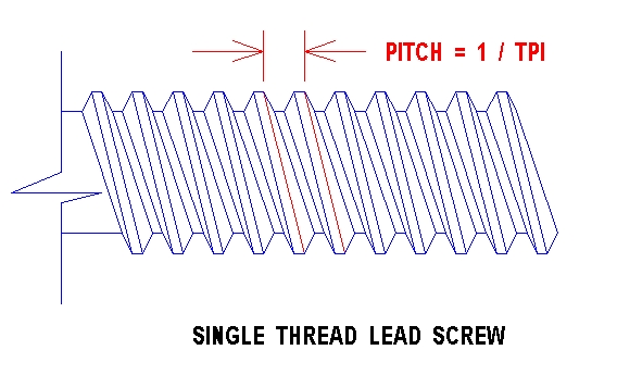
Linear resolution and thrust is also determined by the geometry of the lead screw itself. Lead refers to the linear position that can be achieved through one revolution of the screw within the nut assembly. Consider a single thread, 1/2 inch, 10 TPI (Threads Per Inches) as an example. The pitch is 1 / TPI and describes the distance from crest to crest on adjacent threads. For one rotation, a linear movement of one tenth of an inch would be achieved for this lead screw.
Thrust is also dependent on the leadscrew
geometry. Imagine unwrapping one thread equaling the pitch on a leadscrew.
Essentially, an inclined plane would result. Since the input work
must equal the output work, output force can be determined using the following
relationship:

The drive motor is rated in torque (e.g. inch-ounces), and the input
force on the lead screw can be found as follows:

Thus the mechanical advantage for the leadscrew is output force divided by input force. For a single thread, mechanical advantage is approximately 15.7.

The problem is how to achieve positional resolution. From the geometry of a single thread leadscrew, the lead is equal to 1/TPI = 1/10 = .01 inches/revolution. However, finer resolution is required which is typically one ten thousandth for most CNC machine tools. One method of increasing the resolution control, is using stepper motors. A brief introduction to stepper motors is given in the following section.
Stepper Motors.
Stepper motors are unique in that a discrete angular displacement will result when a voltage is applied. When voltage is applied to the field winding on the stepper motor, an electro-magnetic field is produced. If the armature has a permanent magnet with north and south magnetic fields, a repulsion will exist between the similar magnetic fields, and and attraction to the opposing magnetic fields.

"Stepping" is controlled by the sequence of exciting the field coils in the stepper motor. The CNC controller must generate "pulses" in a specific order to cause rotation of the stepper motor armature. Different motors have different number of steps or pulse requirements to generate one revolution of movement. A typical resolution for CNC stepper motors is 200 steps per revolution or 1.8 degrees per step (this is referred to as the step angle).
Consider a stepper motor with a 1.8 degree step angle coupled to the 1/2 inch, 10 TPI leadscrew. The resolution capability would be as follows:
insert formula here showing how .0005 is possible.
This resolution can be increased to .0001 by using a 1:5 gear ratio from the he stepper motor gear to the leadscrew great as shown below:

Controller Function
Since the stepper motor will increment one step angle per pulse, the controller determines the distance moved by producing a discrete number of pulses. This distance is dependent on the characteristics of the leadscrew AND the step angle of the stepper motor. Therefore, the controller produces and counts the the number of pulses from a square wave generator to control distance moved. Speed of movement is determined by the frequency at which the the pulse train is produced. So the controller must do the following for each axis on the machine tool:
1. Determine the number of steps based on the programed instruction (e.g. X 1.0);
2. Count the number of steps;
3. Delay a specific integer value between pulses to control speed.
A controller has a specific TIMED LOOP CYCLE (Rc) which is the time duration from when a signal is sent to by the controller to the actual response of the stepper motor. This time is primarily governed by the response time of the stepper motor.
Example:
Lets look at our example using the 1/2, 10 TPI leadscrew coupled to a stepper motor having 200 pulses per revolution, and assume a required feed rate is 10 inches per minute. If the Rc value is 40 kHZ, what are the output requirements of the controller for a move one inch on the X axis?

First find the number of steps per inch:
200 pulses 1 revolution
2000 pulses
SPI = ----------
X ----------- X 1
inch = -------------
revolution .10 inches
inch
Second determine the required pulse rate:
PR = SPI X FR
2000 Pulses
10 Inches 1min
333.334 Pulses
= ------------
X ----------
X ------ =
-----------------
Inch
Minute
60 Sec.
Second
Third, determine the delay between pulses:
D = Rc / PR
40 000 Pulses / Sec
= ----------------------
= 120 NOTE: MUST
BE AN INTEGER!
333.334 Pules / Sec.
Angular Movement:
So far, we have only considered linear movement; however, if angular moves are required, two axis are engaged simultaneously as in the case of making a diagonal cut on a milling machine. The problem is to maintain the required feed rate and adjust the delay and number of steps for each individual axis.
Consider the following example: Using the same specifications as before lets now determine the requirements for the X and Y axis to make the following diagonal cut.

We must first determine the total distance for the cutter. In this example, S will be used to represent the required distance.


Next determine the time duration for moving
this distance, based on the required feed rate (10 inches per minute for
this example problem).
t = S / FR
2.236 inches
60 seconds
t = -------------
= .2236 minutes X
------------- = 13.416
seconds
10 inches/min
minute
Now, the Pulse rate x an y can be determined:
X - AXIS
Note: 2000 pulses x 2 inches on the X axis = 4000 pulses.
4000 pulses
298.15 pulses
PRx = -------------
= ---------------
13.416 sec.
second
Rc
40 000 pulses / sec.
Dx = -----
= ---------------------
= 134.16 or 134 (integer value)
PRx
298.15 pulses/sec
Y - AXIS
1 inch of movement required, therefore 2000 pulses.
Note: 2000 pulses x 2 inches on the X axis = 4000 pulses.
2000 pulses
149.076 pulses
PRy = -------------
= ---------------
13.416 sec.
second
Rc
40 000 pulses / sec.
Dy = -----
= ---------------------
= 268.32 = 268 (integer value)
PRx
149.076 pulses/sec
Closed Loop Systems
Closed loop systems typically use d.c. servo motors as opposed to
stepper motors. Feed back is obtained either by using a resolver
or optical encoder as shown below. A pulse train is generated
by the optical encoder. This pulse train can be compared to the pulse train
generated for the axis control value along with the frequency to verify
movement and speed of movement.

Assignment
Using the specifications of 1/2 inch lead screw, 10 TPI, 200 pulses per revolution stepper motor (open loop system). Determine the controller output for the CNC program you wrote in Module 7. Show all work and summarize your answer in table format as follows:
SEQ
X - AXIS
Y - AXIS
Z - AXIS.
No.
Sx PRx
Dx
Sy PRy
Dy
Sz PRz
Dz
__
___ ___
___
___ ___
___
___ ___
___