Laboratory 4 : Drilling Station Control Using Automation Studio and a Siemens PLC
Purpose: The purpose of
this laboratory exercise is to develop a control system for a drilling station using Automation Studio. The
system will be developed using the Siemens PLC
module. The drilling system should be activated by an operator controlled
start
switch. Actuators of the system consist of a feed/clamp cylinder,
drill motor, drill motor feed cylinder, and an ejection cylinder.
A
previously created HMI for the drilling station will be provided.
A start/stop control panel must be added to the existing HMI.
The system processes parts by feeding individual parts from a hopper
and clamping the part into position prior to drilling. After
clamping, a drill motor turns on, and the drilling motor feed cylinder
extends then retracts to create a drilled how. Upon completion
of the drilling operation, an ejection cylinder extends to push the
completed part down the production line. A count should be made
for each good part. The cycle repeats until an operator stops the
system. A simulation will be run to verify the
successful operation of
the system.
Outcomes: After completing this laboratory exercise students should be able to demonstrate the following abilities and skills:
1. Demonstrate basic knowledge and application of
selected modules within the Automation Studio software suite;
2. Demonstrate skills in the use of
Automation Studio to create a Siemens PLC control
program, and link to a HMI panel;
3. Demonstrate knowledge of memory functions internal to the Siements PLC;
4. Demonstrate knowledge of counters required for tracking cycles within a PLC;
5. Demonstrate successful completion of the
laboratory exercise through a verified system simulation;
6. Demonstrate an understanding of the drilling station and control through a written laboratory report.
Deliverables: The following deliverables are required for this laboratory exercise:
1. Drilling system with components clearly labeled;
2. PLC program with all inputs, outputs and functions
clearly identified;
3. Internal connections of a counter within the PLC program;
4. Wiring diagram showing connections of inputs, outputs,
and power source to the PLC output interface module;
5. HMI panel diagram clearly labeled including added operator start and stop functions;
6. Table of all tags used for the laboratory;
7. A formal written report including the following
sections:
I. Abstract (10 points)
II. Problem Statement (5 points)
III. Required System Operation (10 points)
IV. System Diagram (10 points)
V. Procedures (10 points)
VI. Results: (25 points)
A. Sequence Control Chart (5)
B. Symbols Table (5)
C. Tags Table (5)
C. Diagrams (Pneumatic circuit, PLC program, wiring
diagram, HMI panel layout) (10)
VII. System Analysis and Summary (30 points)
A. Detailed explanation of system configuration and operation;
(10)
B. Network by Network explanation of PLC program control; (15)
C. Recommendations (5)
VIII. References
System Overview: The system operation is controlled by an HMI operator interface panel. Once Automation is placed in the
simulation mode and the operator depresses the start button. (Note:A
start/stop control panel must be added to
the existing HMI). The system processes parts by feeding individual
parts
from a hopper and clamping the part
into position prior to drilling.
After clamping, a drill motor turns on, and the drilling
motor feed cylinder extends
then retracts to create a drilled how.
Upon completion of the drilling operation, an ejection cylinder
extends to
push the completed part down the production line. A count
should be made for each good part. The cycle repeats
until an
operator stops the system. A simulation will be run to verify the
successful operation of the system.
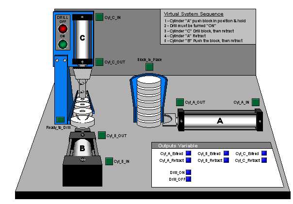
Diagram of Completed System:
An illustration of the system
showing the provided HMI for the drilling station is shown
below.
Procedures
A. 1. Create a list of required inputs and outputs for the PLC
program. Develop a pencil and paper sketch of the PLC program and
identify the basic
components
required. Develop a symbol table with cross referencing.
2. Develop a control sequence
chart showing the logical constraints. The purpose of the chart
is to provide a guide for writing the logical
programming steps. The sequence control chart could be compared
to a flow chart usage for computer programming.
3. Develop a pencil and paper
sketch of the PLC program and identify the basic components required.
B. Load the system HMI as as shown above in Automation
Studio. Follow the procedures as outlined in class lecture by
completing the following steps:
1. Using the Siemens-PLC
module, create the control circuit including all appropriate inputs, outputs, internal memeory functions, and a counter.
2. Using the JIC Electrical Control
Module, create a wiring diam for all inputs and outputs.
Note: The PLC CARDS function provides
for
the connection terminal blocks with addresses and LED's. Select
the INPUT card for input connections, and OUTPUT card for output
connections.
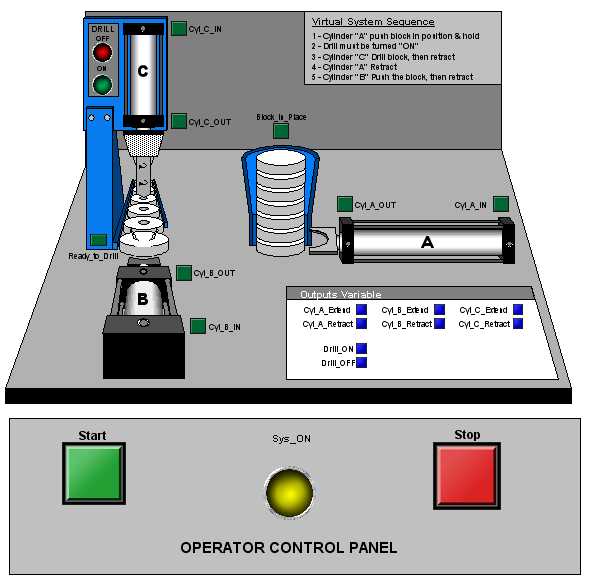
4. Using the provided HMI panel, open the HMI Module and add both
start and stop buttons. Add an indicator lights to show when the system
is active. Create the control panel as shown
below.
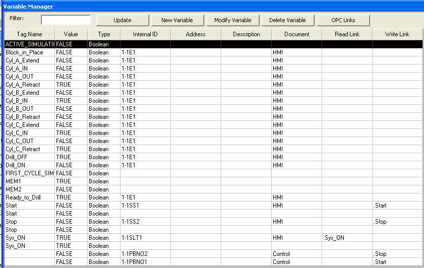
5. Open the Variable Manager and create the appropriate TAGS:
6. Note: Internal tags
will be created automatically when components are created in Automation
Studio. An example of tags within the Variable
Manager is shown below. Your list may be somewhat different, depending
on specify names assigned at the time the tags were created.
7. Link the tags to the appropriate component as demonstrated in class.
C. Run a simulation of the project to test for
functionality. Verify that all active components are simulated
and working properly.
Run the simulation in slow motion or
"step-by-step" and observe the logical operation. Study the
system's operation until you have
a thorough understanding of how the system operates and how control is executed.
D. Using the format specified, complete a written laboratory report and submit by next class period.