Laboratory 1 : Single Actuator Control Using Automation Studio
Purpose: The purpose of
this laboratory exercise is to develop a control system for a simple
linear pneumatic circuit using Automation Studio. The
pneumatic system will be developed using the pneumatic module within
Automation studio, and an Allen-Bradley PLC module will be used
to provide the control program for the pneumatic circuit.
Discrete inputs, outputs, and power supplies will be virtually wired to
PLC I/O cards to
simulate a real world system using the JIC electrical control
module. Finally, a simulation will be run to verify the
successful operation of the system.
Outcomes: After completing this laboratory exercise students should be able to demonstrate the following abilities and skills:
1. Demonstrate basic knowledge and application of
selected modules within the Automation Studio software suite;
2. Demonstrate skills in the use of
Automation Studio to create a pneumatic circuit, PLC control
program, and simple HMI panel;
3. Demonstrate knowledge of wiring configurations required for
input and output devices connected to a PLC;
4. Demonstrate knowledge of basic HMI functions and
create a virtual interface operator panel;
5. Demonstrate successful completion of the
laboratory exercise through a verified system simulation;
6. Demonstrate an understanding of the pneumatic
system and control through a written laboratory report.
Deliverables: The following deliverables are required for this laboratory exercise:
1. Pneumatic circuit with components clearly labeled;
2. PLC program with all inputs, outputs and functions
clearly identified;
3. Wiring diagram showing connections of inputs and power
source to the PLC input interface module;
4. Wiring diagram showing connections of outputs
and power source to the PLC output interface module;
5. HMI panel diagram clearly labeled;
6. Table of all tags used for the laboratory;
7. A formal written report including the following
sections:
I. Abstract (10 points)
II. Problem Statement (5 points)
III. Required System Operation (10 points)
IV. System Diagram (10 points)
V. Procedures (10 points)
VI. Results: (25 points)
A. Sequence Control Chart (5)
B. Symbols Table (5)
C. Tags Table (5)
C. Diagrams (Pneumatic circuit, PLC program, wiring
diagram, HMI panel layout) (10)
VII. System Analysis and Summary (30 points)
A. Detailed explanation of system configuration and operation;
(10)
B. Network by Network explanation of PLC program control; (15)
C. Recommendations (5)
VIII. References
System Overview: The system operation is controlled by an HMI operator interface panel. Once Automation is placed in the
simulation mode and the operator depresses the start button, the
pneumatic cylinder should extend, retract,
and repeat this cycle until the operator depresses the
stop button. The states components will be indicated
by a color change during the execution of the simulation.
Diagram of Completed System:
An illustration of the system
showing the HMI panel, pneumatic circuit, input wiring, PLC program,
and output wiring is shown
below.
Procedures
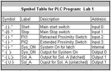
A. 1. Create a list on required inputs and outputs for the PLC
program. Develop a pencil and paper sketch of the PLC program and
identify the basic
components
required. Develop a symbol table with cross referencing.
Your table should look similar to the example shown below.
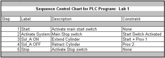
2. develop a control sequence
chart showing the logical constraints. The purpose of the chart
is to provide a guide for writing the logical
programming steps. The sequence control chart could be compared
to a flow chart usage for computer programming. An example is shown
below.
3. Develop a pencil and paper
sketch of the PLC program and identify the basic components required.
B. Create the system as as shown above in Automation
Studio. Follow the procedures as outlined in class lecture by
completing the following steps:
1. Using the pneumatic
module, create the basic pneumatic circuit including a Directional
Control Valve (DCV) with single solenoid control,
air source and exhausts,
differential cylinder, two proximity switches, and connecting lines.
2. Using the JIC Electrical Control
Module, create a wiring diam for inputs and outputs as shown.
Note: The PLC CARDS function provides
for
the connection terminal blocks with addresses and LED's. Select
the INPUT card for input connections, and OUTPUT card for output
connections.
3. Using the "Ladder for AB PLC" Module, create the PLC logic as shown above.
4. Using the HMI Module, create the control panel as shown.
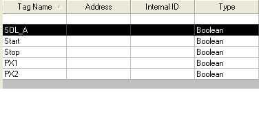
5. Open the Variable Manager and create the following TAGS:
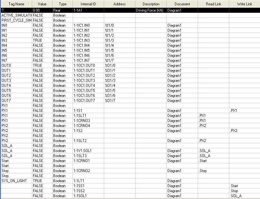
6. Note: Internal tags
will be created automatically when components are created in Automation
Studio. An example of tags within the Variable
Manager is shown below. Your list may be somewhat different, depending
on specify names assigned at the time the tags were created.
7. Link the tags to the appropriate component as demonstrated in class.
C. Run a simulation of the project to test for
functionality. Verify that all active components are simulated
and working properly.
Run the simulation in slow motion or
"step-by-step" and observe the logical operation. Study the
system's operation until you have
a thorough understanding of how the system operates and how control is executed.
D. Using the format specified, complete a written laboratory report and submit by next class period.