ET 449: ADVANCED TOOLING AND PROTOTYPING
Week Topic Lab .
1 Optimizing Tool Paths for Production Simple Sub-assembly
2 High Speed Machining Sub-assembly rework
3 Lathe Operations External Threaded Shaft
4 Mill Operations Internal Threads
5 Fourth Axis Machining Positional Indexing
6 Full 4th Axis Machining Impellor or Gear
7 3-D Machining Simple Mold
8 Lazer Machining I.D. Tag or License Plate
9 Semester Project Planning Reverse Engineering and Parametric Design
10 Production Planning Group Project Work
11 Production Machining Group Project Work
12 Advanced CAM Operations Group Project Work
13 Advanced CAM Operations Group Project Work
14 Advanced CAM: Complex Surfaces Group Project Work
15
Final Exam
Lab Clean Up
Week 1
Introduction
Syllabus
Scope of Course
CNC Basics and SurfCam review
FEEDS AND SPEEDS
In general, referenced speeds and feed data are
for beginning points. Adjustments
may be necessary to compensate for the variables
above. Make sure referenced
data matches the type of operation and variables
show above as closely as possible.
SPEED CALCULATIONS:
RPM: GENERAL FORMULA:
RPM = CS / CIRCUMFERENCE
ENGLISH: RPM = FT. x 12 in. x
1 REV
Min. Ft
px D
METRIC: RPM = m x
1000 mm x 1 REV
min.
m px
D
NOTE: D =
DIAMETER:
FOR TURNING, D = DIAMETER OF STOCK
FOR DRILLING, REAMING, MILLING, D = DIAMETER OF TOOL.
FEED RATES:
TURNING: Refer to Tables for Turning:
General Recommendation
for low carbon steel: .007 -.010 in. per revolution (.25 - .4 mm/rev)
is used for roughing.
Finishing feeds are .001 - .003 in. per revolution (.07 - .12 mm/rev)
MILLING: Fr = N x T x RPM
where: N = Number of Teeth
Fr = Feed rate in IPM (or mm per minute for metric)
T = Feed per Tooth per Revolution
RPM = Revolutions per minute = CS/Circumference
MACHINING TIME:
LATHE: MT = LENGTH / (FEED X RPM); MT = L / (F X N)
MILL: MT = LENGTH / (FEED RATE); MT = L / ( fr )
MAKE SURE APPROPRIATE
TABLES ARE CONSULTED FOR MATERIAL
AND CUTTING TOOLS
BEING USED.
NOTE: THERE ARE TWO TYPES OF MILLING:
UP MILLING (CONVENTIONAL MILLING) - Chips are carried
away from the base stock.
Down Milling (Climb Milling) - Chips are carried into the base stock.
In general, UP
Milling is recommended for older equipment and lower horsepower
machine tools, and less
rigid setups. In climb milling there is a tendency for the cutter
to "climb over the work"
if the setup is not rigid.
Post processing procedures
Fixturing and Tooling considerations
Set Up Sheets and Operator Procedures
HAAS VF-1 Introduction
Controller
Layout
Navigating through MENUS
Setting Workplanes G54
Setting Tool Offsets
File Importing
Graphical Simulation
ASSIGNMENTS
Review the HAAS
controller layout
Navigating through MENUS:
Note: Visit the HAAS website and review the controller layout.
Complete all necessary
preparatory work for lab one (i.e. complete parametric mode, dwg, dxf,
i.d. tooling, assign tool number).
Lab 1 Prep work : TO
GO TO LAB 1 CLICK HERE.
CYCLE TIME
REDUCTION AND OPTIMIZATION
NOTES ON NEXT LABS 3,4,5.
The following illustraions show the logical
progression of steps to produce a fixture (Lab3), thread milled hub (Lab4),
and
hexagonal flats cut using the 4th axis (Lab5).
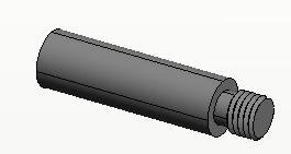
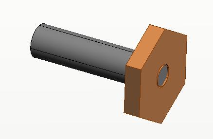
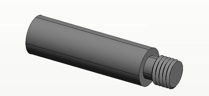
LAB 3: MACHINE A 1 INCH DIAMETER THREADED SHAFT TO BE USED AS A MOUNTING FIXTURE.
LAB 4: MACHINE A 3 INCH DIAMETER HUB BY THREAD MILLING THE CENTER HOLE.
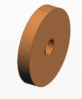
LAB 5: MOUNT THRADED HUB (LAB4) ON THREADED SHAFT (LAB3)
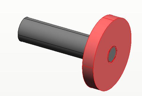
LAB 5 CONTINUED: MILL 6 FLATS TO FORM A HEXAGONAL HUB USING 4th AXIX
POSITIONING METHOD
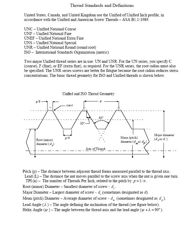
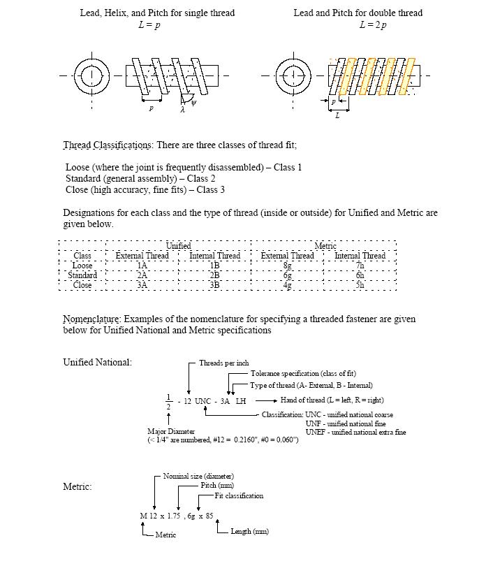
Purpose: This exercise will cover the basic procedures for Outside Diameter (O.D.) turning and external threading operations in OneCNC. File importing, coordinate systems, CNC options, tool selection, and toolpath generation will be covered.ET 449
CNC LATHE OPERATIONS: O.D. TURNING and External Threading
LABORATORY 3
Objectives: After completing this exercise you should be able to perform the following:
1. Import an IGES file into OneCNC
2. Edit the file for delineating required geometry
3. Set the coordinate system for the lathe operations
(lathe radius)
4. Select the geometry to be turned
5. Specify tooling information required
6. Modify cut control as necessary
7. Generate a tool path for the part specified
8. Post-process tool path for a HAAS lathe
9. Save the file as a PLAIN ASCII format
10. Download file to the HAAS TL-1 lathe
11. Run the program (under supervison) and produce
the required part.
Procedures:
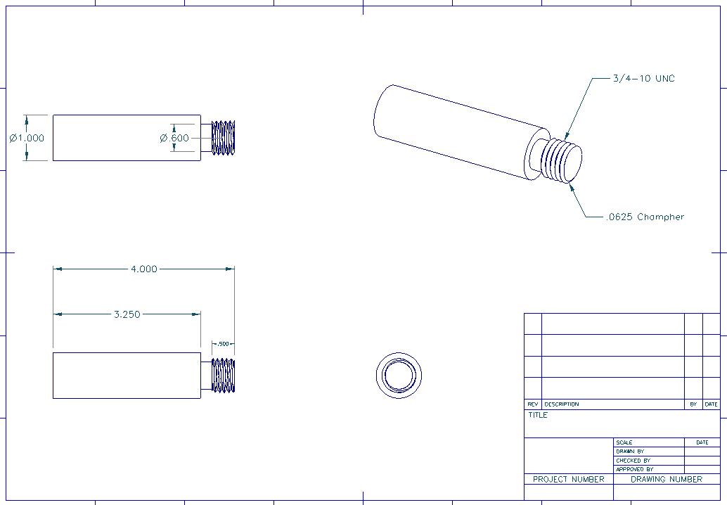
Prior to using OneCNC, create a model or 2D drawing of part shown in the following section. You may create the geometry using a 3D package of your choice (i.e. ProE, ProD) or create using AutoCad or equivalent.
Steps necessary for creating a toolpath are provided with graphical
illustrations .
Major steps include the following:
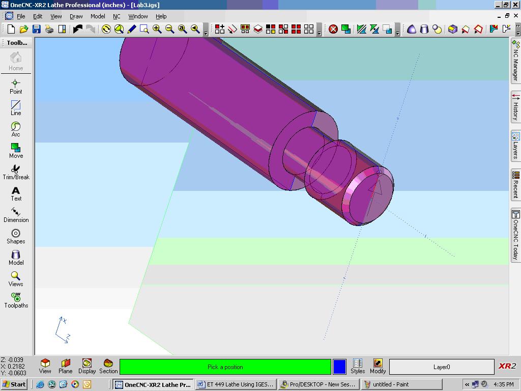
STEPS: ET 449 Lathe 3D Model Import Method
1. Create 3D parametric model. Make sure 0,0,0 is located on the
right end, at center.
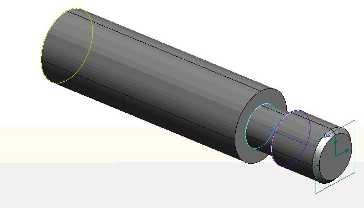
2. Export IGES file
3. Open OneCNC Lathe Professional
4. Import IGES file
5. From the menu, select MODEL: Extract Lathe Profile
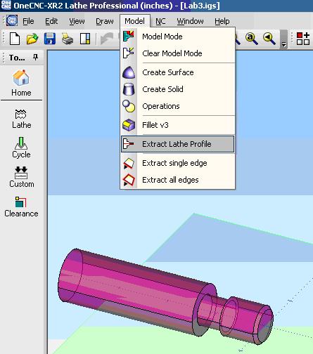
6a. A blue outline will be generated representing the lathe profile
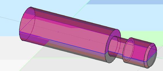
6b. For facing, the line show must be broken and trimmed so facing
will only occur from the center of the part outward (radius).
7. From the Edit menu, select Break, Divide and click on the like as shown in step 6.
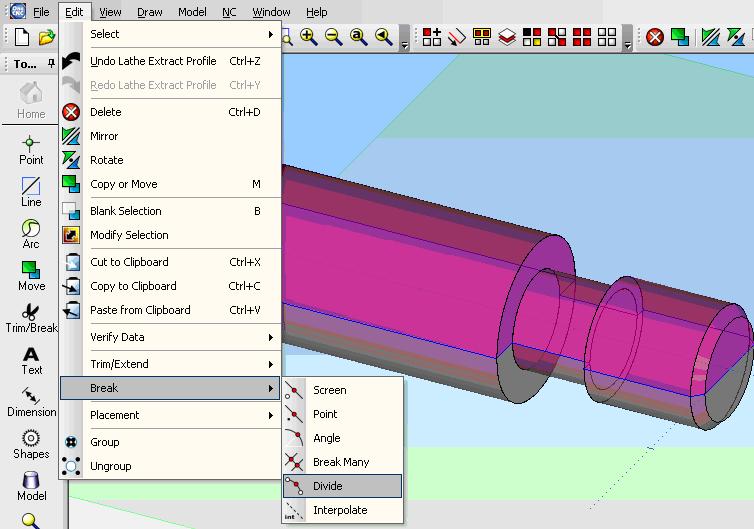
Note: Select the number of divisions = 2.
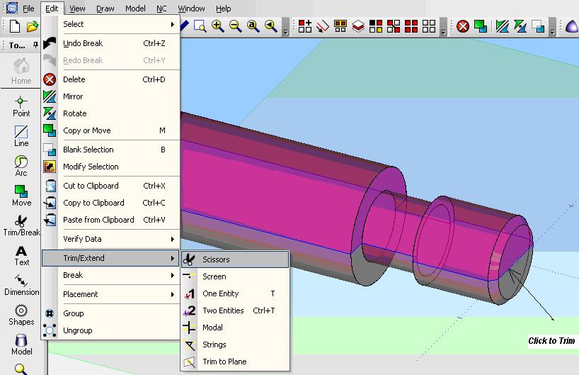
8. Trim the bottom half of the line as shown below:
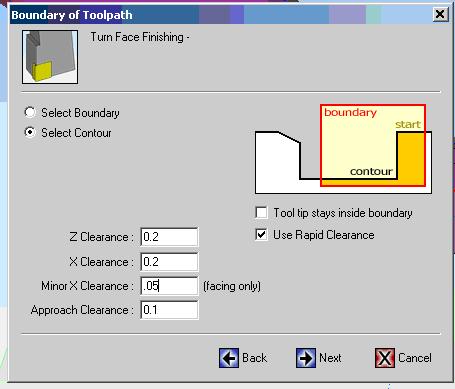
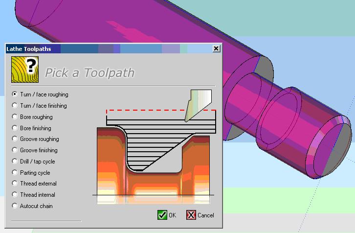
9. Select Lathe Toolpaths and pick Turn/face finishing
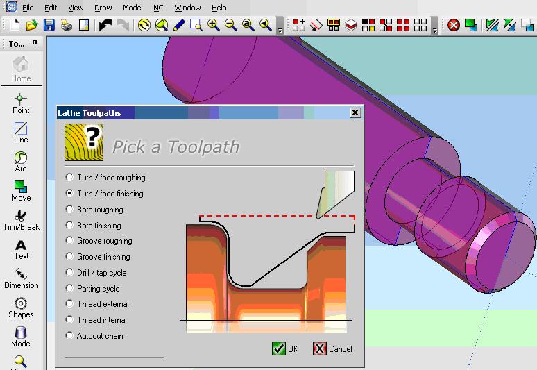
10. Select the line as indicated below for facing, then select end point.
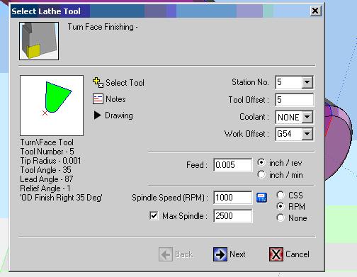
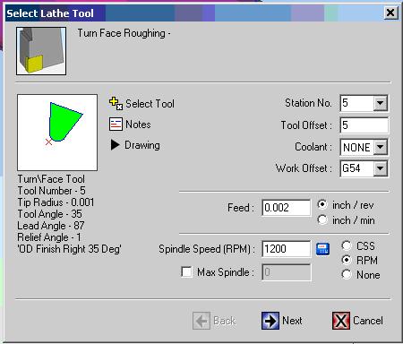
11. Select the tool (for this lab we will use a VNMG 35 degree) tool.
Station should be 5 and tool offset should be 5. Select coolant none
and Work Offset to G54
Specify feed rate for inches/rev between .003 and .005. Select
RPM, Spindle speed = 1000 to 1400 RPM (for acetyl).
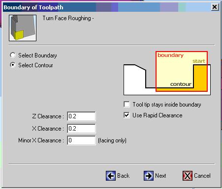
12. Enter values as show for facing operation, then click Next.
13. Enter values as shown in the final dialogue window for the facing
operation.
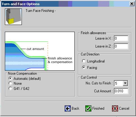
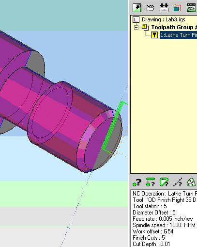
You should now have a toolpath for the facing operation:
14. Create a ROUGHING operation:
15. Next Pick the profile geometry for the roughing operation as shown
below then right mouse click to select (use the same VNMG tool #5).
16. Enter the values as show on the next two dialogue windows, then
click Finished.
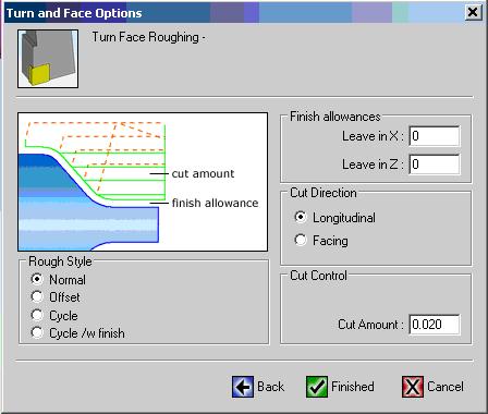
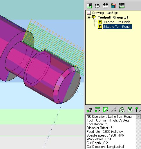
17. You should have a toolpath similar to the one shown below:
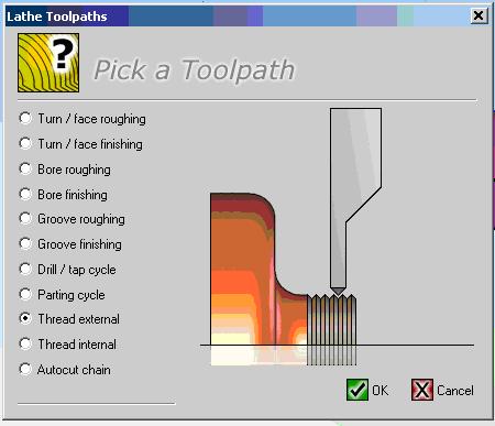
18. Next Create a Threading toolpath: Select External Threading
from the menu as shown:
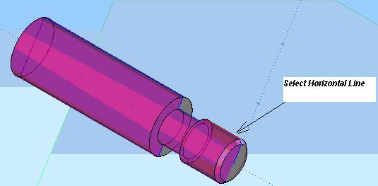
19. Next select the line for the thread geometry as shown:
20. Enter the information in the dialogue windows as shown (note enable
editing
and change the tool information as indicated (change tool angle to
60 deg.)
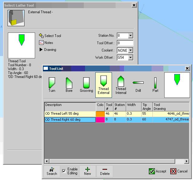
21. Click Accept and verify tooling information is as shown below:
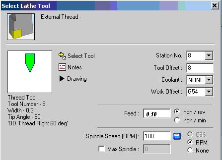
22. On the next screen, enter the information as shown below:
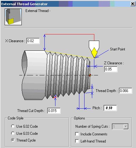
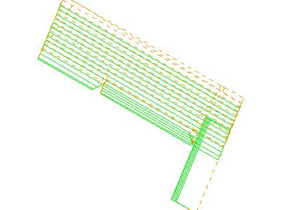
23. Click NEXT, then click FINISHED. You should see a backplot
of the toolpath
similar to the one shown below:
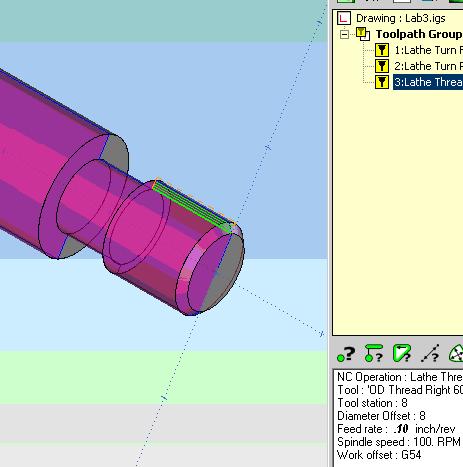
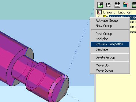
24. Click on NC Manager and select PREVIEW TOOLPATHS. Make sure
TOOLPATH GROUP is highlighted.
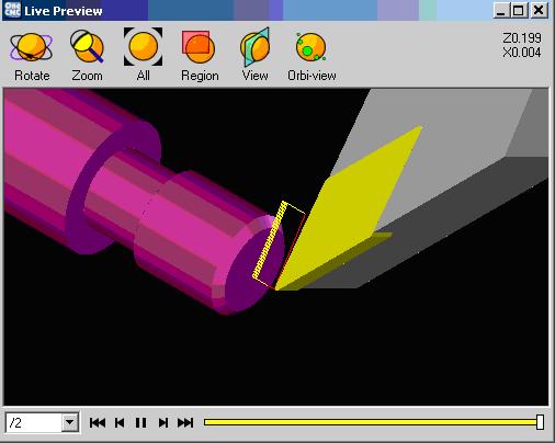
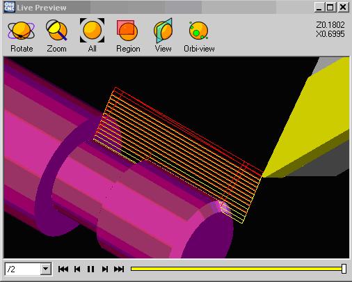
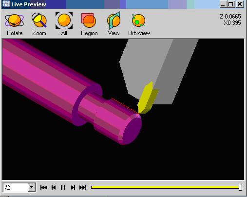
25. You should see a series of tool paths generated on the screen similar
to the ones
shown below:
FACING
ROUGHING
THREADING
26. You are now ready to post process: Make sure HAAS is the post
processor
selected prior to posting as shown: After posting, the file is
ready for download to the HAAS SL20 CNC lathe.
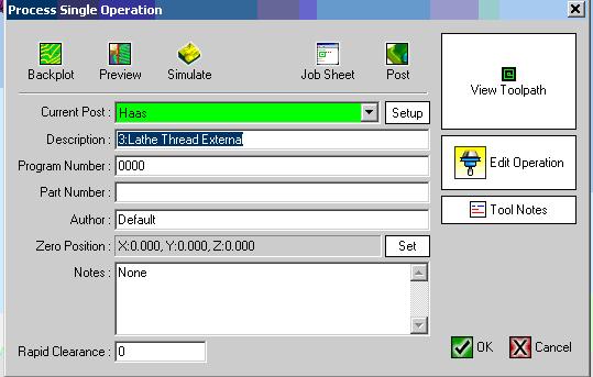
27. You may also want to print a JOB SHEET as depicted below:
JOB SHEET (Toolpath Group #1)
Post Used - Haas
Post Date - Sunday, January 28, 2007 (17:34)
Time to Machine - 25 minutes 52 seconds
Filename - C:\Documents and Settings\ball\Desktop\Lab3.igs
Part Number -
Program Number - 0000
Time of Creation - Sunday, January 28, 2007 16:16
Last Modified - Sunday, January 28, 2007 16:16
System Used - OneCNC-XR2 Lathe Professional - Version 7.33
Author - Default
Notes - None
OPERATIONS
Total number of operations - 3
Operation #1 (1:Lathe Turn Finish)
Operation time - 1 minutes 8 seconds
Tool - Station #5 : OD Finish Right 35 Deg (Turn/Face, 0.38 Dia, 0.00
Tip, F0.005, S1000 RPM)
Operation #2 (2:Lathe Turn Rough)
Operation time - 15 minutes 53 seconds
Tool - Station #5 : OD Finish Right 35 Deg (Turn/Face, 0.38 Dia, 0.00
Tip, F0.002, S1200 RPM)
Operation #3 (3:Lathe Thread External)
Operation time - 8 minutes 51 seconds
Tool - Station #8 : OD Thread Right 60 deg (Thread, 0.30 Dia, 0.00
Tip, F0.1, S100 RPM)
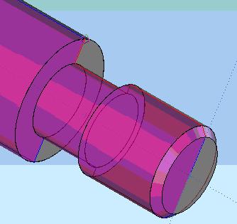
The following part will be produced on a HAAS CNC lathe.
Threads can be produced in several different manners using CNC machine
tools. Some of these methods include:
A good introduction to threads and fastners can also be found at the following websites:http://www.mech.uwa.edu.au/DANotes/threads/intro/intro.html
http://www.jjjtrain.com/vms/cutting_tools_hand_tap.html#1
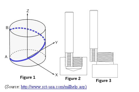
Threads can be produced in several different manners
using CNC machine tools. Some of these methods include:
THREAD MILLING: NOTE THAT CUTTER MOVES IN A HELICAL PATH. Any CNC having helical interpolation can cut threads