ET 349 Rapid Prototyping and Tooling:ASSIGNMENTS
ASSIGNMENT 1 (BEGIN IMMEDIATELY)
REVIEW AND STUDY THE SAFETY RULES GIVEN IN
LABORATORY 1. SIGN AND TURN IN THE
LAB SHEET TO YOUR LAB INSTRUCTOR. THIS
IS YOUR TICKET TO ENTER THE MACHINING
LABORATORY!
Visit the HAAS web site and review the section on the HAAS controller.
http://www.haascnc.com/solutions_control.asp#controlBECOME FAMILAR WITH THE HAAS MACHINE TOOL AND CONTROLLER!
Download a copy of the HAAS G & M codes for your personal reference.
http://www.haascnc.com/training/MillProgram_PDF/xMGMCard.pdf
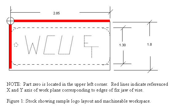
1. Study the drawing shown in Figure 1, and identify
the maximum machineable area for the work
part to be produced. Note that pre-sized stock
will be provided that conforms to the dimensions shown.
The first step for this lab exercise will be the creation
of a luggage tag. You have the choice of designing
the product as you wish within the constraints as follows:
The name plate must display WCU and ET
in some manner and fit within the allowable work space.
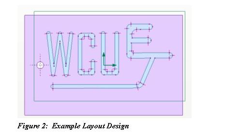
Since you will writing the program manually,
it is suggested that the layout be kept relatively simple.
There are two machining operations that must
be performed: 1) WCU and ET text; and 2) A drilled
1/8” hole to accept a chain, string, or strap for
mounting. Your layout design could look something
like what is shown in Figure 2.
2. Go to the following website and download a copy of the MACH3 CNC software (free for educational use in demo mode).
http://www.machsupport.com/downloads.php
Use the following STANDARD TEMPLATE
for your first manual CNC program.
%3. Visit the following websites and become familiar with the HAAS controller. Study each section so that you
O0001 (Program Name)
N05 G20 G40 G49 G54 G80 G90 G98
N10 M06 T01
N15 G43 H01
N20 M03 S1200
N25 G00 X0.0 Y0.0 (M08)
N30 G00 Z.2
N35
N40 (PLACE CODE HERE)
N45
N50
N97 G91 G28 Z2.0
N98 M05
N99 M30
%
http://www.haascnc.com/solutions_control.asp#control
ASSIGNMENT 3
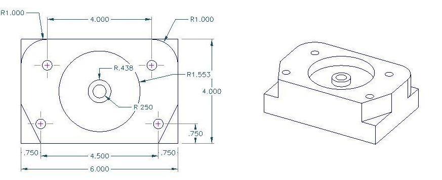
1. Study the drawing shown in Illustration 1,
and identify the geometry to be machined. Note that pre-sized
stock will be provided by the lab instructor.
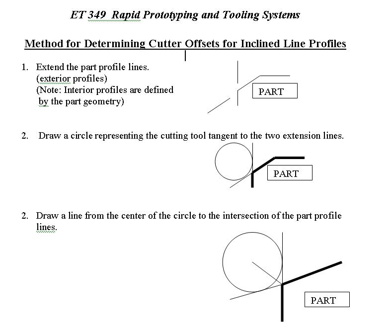
The first step for this lab exercise will determining tool path
coordinates. Tool path coordinates for
NORMAL lines (horizontal and vertical) can be found by offsetting
the part object lines by a value equal to the radius
of the cutter to be used. For this laboratory exercise,
a ¼ 4 flute end mill will be selected.
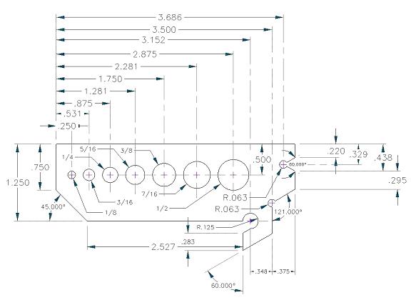
Illustration 1: Drill Index and Angle Gage
Develop a CNC program using AutoEdit software to
produce the provide of the part. See the illustration
below. You must calculate the offset and
machine tool coordinates for generating the toolpath (as
shown in green). A guide for calculating
coordinates is provided in the next section.
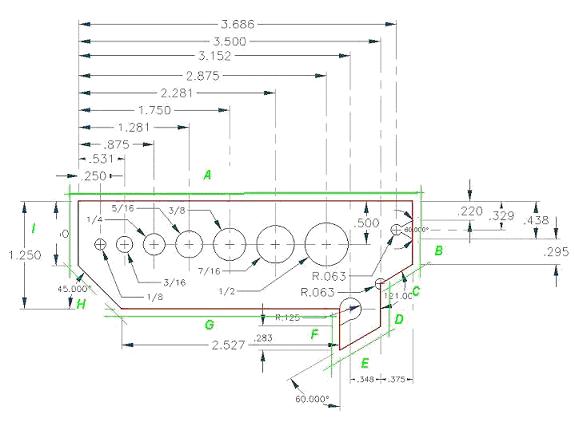

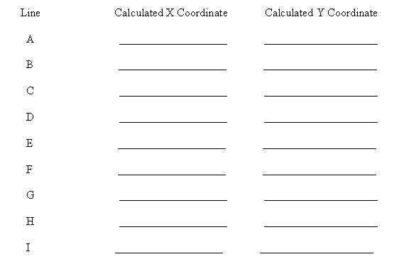
Calculate the coordinate values for the lines marked
as follows and record in the spaces provided below
(Note: attach a copy of manual calculations
as an appendix to the lab write up). Starting in the upper
left
hand corner of the part (0,0), determine the end point
of the first line (A). This coordinate will become the
beginning of line B. Continue CLOCKWISE around
the part and determine the endpoint coordinates for
each of the remaining lines and record below.
Download AUTOEDITNC and write the CNC code for Lab 3.
OPERATOR:____________________________ DATE:______
TIME:_____
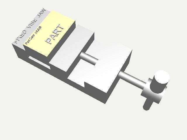
PART NAME: VALVE BODY
PART # EX1
PART MATERIAL: 6061-T6 ALUMINUM
TOOL MATERIAL: M2 HSS
TOOL(S) TYPE: .5 " END MILL
TOOL # 10 COOLANT : FLOOD
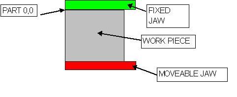
PART ZERO LOCATION (upper right corner of part) WORK
PLANE: G 54
SPECIAL INSTRUCTIONS:
SETUP PROCEDURES:
1.
2.
3.
4.
5.
6.
.
.
.
N
INCLASS DEMO on ONECNC: Machining the part shown below (profiling,
pocketing, drilling, reaming)
RPM = CS x FT. x 12 in. x Rev
= 3.82 CS
Min FT
?D
D
Where: CS = Cutting Speed of the material in FEET PER MINUTE
D = Diameter of the cutter (or stock for lathe) in inches
Similarly, Feed Rate can be calculated as follows:
FR = FPT x t x RPM
Where: FPT = Feed per cutter tooth per revolution in thousandths
of a an inch
(English System).
t = Number of teeth on the cutter (no units)
RPM = Revolutions per minute of cutter.
How units cancel: FR (in/min) = in/tooth
x t (teeth) x Rev
Rev
Min
Today’s Notes on SurfCAM:
CAD Side: Used mainly for editing and manipulating drawings
CAM Side: NC - Used to create CNC tool paths
Verify – Produces a graphical simulation of tool path
POST - Post Processes code to machine executable format
General Steps for Producing CNC programs (2D):
1. Import DXF file
2. Strip unwanted text and geometry
3. Move to point (0,0) Note this is the G54 Workplane.
4. Select the geometry to be machined
5. Specify machining and set up information
6. Save file
7. Post-process
8. Save to 3 ½ floppy disk
9. Transfer to HAAS CNC Machine
1. SIGNED Safety Sheets should
be on file.
2. Lab 2 (Luggage Tag) should
have been completed.
3. Lab 3 (Drill Index should
be completed by September 20th, lab report due, September 25th).
4. Complete Lab 4 as soon as
possible (no machining of the actual part will be performed).
5. Complete Lab 5 as soon as
possible (afer lab 4). Again no actual part will be machined.
6. Drawings will be provided
for your semester project not later than Septemb er 25th.
7. Each lab group will be responsible
for setting up a production system to produce the steam engines
(one
for each class member, plus one extra for display).
Note:
You will be responsible for modeling parts, checking assemblies for tolerances,
fits, etc prior to
using the CAM software to produce any part. All parts much have complete
documentaion
including set-up sheets. You will NOT machine the part you produced,
but rater a team member
will machine the part from your specific documentation and instructions.
8. NOTE: We will complete
a ONECNC LATHE LAB simular to the same format as labs 4 and 5. However,
actual
parts will be machined in order to familarize you with the HAAS lathes.
9. The mid-term exam will be given
on October 9th.
10. The second half of the semester
we will focus on your project. Most laboratory work will be dedicated
to
project
work. Extra lab time will be provided.